What Is a Variable-Pitch Propeller?
A variable-pitch propeller (also called a constant-speed propeller in its most common form) is a propeller whose blade angle can be changed during flight. Unlike a fixed-pitch propeller — which is ground-adjusted and then locked — a variable-pitch propeller lets the pilot (or an automatic governor) select the most efficient blade angle for every phase of flight. The result is that the engine can develop maximum power at takeoff, cruise efficiently at altitude, and descend without over-speeding, all without the pilot manually adjusting blade angle on each propeller blade individually.
Understanding the governing mechanism is not just test-prep material — it is a genuine safety topic. A governor failure, an oil system problem, or a propeller that runs away to flat pitch can destroy an engine in seconds. Commercial pilots must know this system from first principles.
Blade Angle Fundamentals
Every propeller blade is an airfoil. The blade angle (sometimes called pitch angle) is measured between the blade chord line and the plane of propeller rotation. A low (fine) pitch gives a small angle of attack relative to the oncoming air — good for high RPM and takeoff thrust. A high (coarse) pitch gives a large blade angle — good for cruise, where the aircraft is moving faster and a coarser bite through the air is more efficient.
The angle of attack of the blade changes with both blade angle and aircraft forward speed. As airspeed increases with a fixed blade angle, the relative wind vector rotates, reducing blade angle of attack and tending to slow the engine. The governor's job is to compensate automatically so RPM remains constant despite these changes.
How the Governor Works
The governor is an engine-driven pump and speed-sensing device mounted on the accessory case. Its three main components are:
- Flyweights: Two or more rotating weights driven at a speed proportional to engine RPM.
- Speeder spring: A calibrated spring that opposes flyweight centrifugal force. The pilot's propeller control lever changes the compression of this spring, which is how the pilot selects RPM.
- Pilot valve (or spool valve): A precision sliding valve that ports high-pressure oil to — or drains oil from — the propeller pitch-change mechanism.
The governor operates around an on-speed condition: the point at which flyweight centrifugal force exactly balances speeder-spring force. When the engine is exactly on the selected RPM, the pilot valve is centered, oil flow is blocked, and the blade angle holds steady.
Overspeed (High RPM)
If RPM rises above the selected value — say, because the pilot reduced power on a descent — the flyweights fly outward with greater centrifugal force, overcoming the speeder spring and lifting the pilot valve. High-pressure oil is ported to the propeller mechanism to increase blade angle (coarsen pitch). A coarser pitch creates more drag on the blade and slows the engine back to the selected RPM. This is called an overspeed condition.
Underspeed (Low RPM)
If RPM falls below the selected value — for example, because the pilot added power — the flyweights move inward, and the speeder spring pushes the pilot valve down. Oil is drained from the propeller mechanism, and spring force (or counterweights on the blades) decreases blade angle (fines pitch). Fine pitch reduces blade drag, lets the engine accelerate, and brings RPM back to the selected value. This is called an underspeed condition.
The Propeller Pitch-Change Mechanism
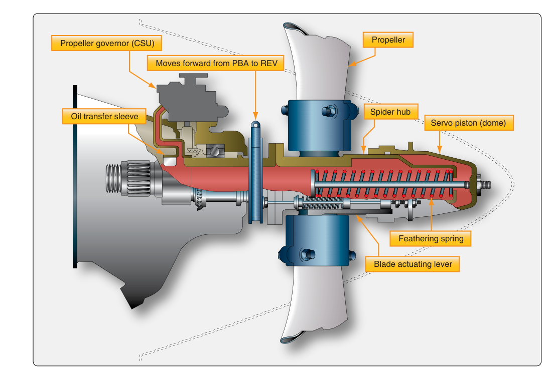
Most single-engine and light twin constant-speed propellers use engine oil pressure as the working fluid. A hollow crankshaft and propeller shaft carry oil from the governor into the propeller hub. Inside the hub, oil pressure acts on a piston connected via a fork or cam mechanism to the blade roots. As oil pressure rises, the piston moves and rotates each blade toward coarse pitch (high angle). When oil pressure is reduced, a counterweight attached to each blade root (or a spring in some designs) rotates the blade toward fine pitch (low angle).
This is a critical safety point: loss of oil pressure causes the blades to move toward fine (low) pitch in most single-engine aircraft propeller designs. Fine pitch prevents a propeller overspeed on engine failure — the blade takes a smaller bite, reducing torque load. However, in some designs (especially older full-feathering systems), counterweights are arranged so that loss of oil pressure moves blades toward feather (high pitch), which is safer for twin-engine operations because a feathered propeller produces less drag than a windmilling one.
Feathering Propellers
A feathering propeller can rotate its blades to approximately 90° blade angle — parallel to the airflow — so that the propeller produces virtually no drag when the engine is shut down. This capability is essential on multi-engine aircraft: a windmilling (unfeathered, failed-engine) propeller creates enormous drag that can make the aircraft nearly impossible to control.
To feather, the pilot moves the propeller control lever to the feather detent (full aft, past the low-RPM stop). This releases all speeder-spring tension, allowing the flyweights to port the pilot valve to maximum coarse position. In most designs, an accumulator stores residual oil pressure so feathering can be completed even after the engine has stopped producing oil pressure. Once feathered, the propeller may stop rotating entirely, eliminating both drag and gyroscopic effects.
Unfeathering (restarting the propeller in flight) requires oil pressure to return the blades toward fine pitch. Many aircraft have an unfeathering accumulator — a pressurized reservoir — that holds enough oil to move the blades to a windmilling angle so the engine can restart from airflow.
Reverse Pitch
Some turboprop and high-performance reciprocating aircraft use reverse pitch — blade angles beyond flat pitch, past the 0° point, into negative angles. Reverse pitch creates reverse thrust, dramatically shortening landing roll. A beta range of pitch (below the normal governing range) and a dedicated reverse-pitch gate on the power lever protect against inadvertent ground use. Reverse pitch is not permitted in flight in most aircraft and is mechanically blocked to prevent unsafe use.
Constant-Speed Operation: Practical Technique
On aircraft with both a throttle and a propeller control, the standard power-change procedure prevents over-boosting and over-speeding:
- Increasing power: Increase RPM first (fine pitch), then advance the throttle (manifold pressure). This ensures the propeller can absorb the additional power without over-stressing the engine.
- Decreasing power: Reduce throttle (manifold pressure) first, then reduce RPM (coarsen pitch). This prevents a condition where manifold pressure exceeds RPM limits.
A common memory aid is: RPM before MP going up; MP before RPM going down — matching the order in which each control should be moved to protect the engine.
Governor Failure Modes
If the governor fails, the propeller typically defaults to whatever blade angle the oil pressure was holding at that moment, or travels toward fine pitch (low angle) if oil pressure is lost entirely. A runaway propeller — one that goes to fine pitch at high power — can cause an engine overspeed, which may exceed the structural limits of the rotating assembly. Pilots must immediately reduce throttle and, if possible, reduce airspeed to bring RPM within limits. Propeller governors are tested during runup: the pilot briefly increases RPM into the governor range and then moves the prop control forward and aft to confirm the governor responds correctly.
Memory Aid
For propeller governor states, remember: FLY — Flyweights, Load, Yield. When RPM is too high, flyweights FLY out, they LOAD the oil port, and the blade angle is driven high, causing RPM to YIELD back to target. When RPM is too low, the process reverses: flyweights fall inward, oil drains, blade angle falls, and RPM climbs. The speeder spring is always the opposing force the pilot pre-sets with the prop control.
Common Test Traps
- Oil pressure and pitch direction: On most single-engine aircraft, increasing oil pressure increases blade angle (coarsens pitch). Loss of oil pressure moves blades toward fine pitch — not feather. Know which design your aircraft uses.
- Overspeed vs. underspeed: An overspeed means the engine is running faster than selected; the governor responds by coarsening pitch. Students often confuse the direction of correction.
- Power change order: The FAA expects RPM before manifold pressure when increasing power. Reversing the order is one of the most frequently tested procedural mistakes.
- Feathering oil source: Feathering is accomplished by releasing oil (in most designs), not adding it — the counterweights and blade design move blades to feather when oil pressure is removed. Some designs use accumulators to complete feathering after engine stoppage.
- Reverse pitch is a ground operation: Engaging reverse in flight is abnormal/emergency only and mechanically prevented in most certified aircraft — don't confuse beta range management with normal flight governing.