Modern light aircraft rely on a carefully designed electrical system to power everything from the radio stack and navigation instruments to landing lights, fuel pumps, and starter motors. Unlike the complexity found in transport-category jets, a typical general aviation (GA) aircraft electrical system is surprisingly straightforward — but that simplicity makes it even more important to understand thoroughly. A mishandled electrical failure, an improperly sequenced master switch, or an undetected alternator fault can escalate from a minor inconvenience into a genuine emergency. For the private pilot candidate, the electrical system is both a common test topic and a critical real-world skill.
This article walks through the components of a typical single-engine GA aircraft electrical system, explains how current flows from the battery through the master switch to the bus bar and individual loads, and describes how to recognize and respond to electrical anomalies. All content is grounded in the FAA Pilot's Handbook of Aeronautical Knowledge (PHAK).
Core Components of the Aircraft Electrical System
A typical light aircraft electrical system operates on 14 volts DC (direct current), though larger aircraft and many twins use 28-volt DC systems. The key components are the battery, alternator (or generator in older aircraft), voltage regulator, master switch, ammeter or loadmeter, bus bar, and individual circuit breakers or fuses protecting each load.
The Battery
The aircraft battery serves two primary functions: it provides power to start the engine, and it acts as a backup power source if the alternator fails in flight. Most GA aircraft use a 12-volt lead-acid battery (in a 14-volt system) or a 24-volt battery (in a 28-volt system). The battery is typically rated in amp-hours, which indicates how long it can sustain a given load before becoming depleted. The PHAK does not publish a standard endurance time for how long a battery can power essential avionics after an alternator failure — actual endurance varies significantly with battery condition, age, and the electrical load carried, which is why shedding nonessential loads immediately after an alternator failure is so important.
The Alternator
Once the engine is running, the alternator takes over as the primary source of electrical power. Driven by the engine crankshaft via a belt or direct coupling, the alternator produces alternating current (AC) internally, which is then converted to DC by internal diodes (a rectifier). The alternator output voltage is regulated to exceed battery voltage by a small margin so that it charges the battery continuously during normal flight while simultaneously powering all aircraft loads — the exact regulated voltage varies by aircraft and voltage regulator setting rather than being a fixed FAA-specified figure. Older aircraft use generators instead of alternators; generators are less efficient at low RPM, which is why early, generator-equipped aircraft sometimes showed a discharge at idle.
The Voltage Regulator
The voltage regulator is an automatic control device that holds alternator output voltage within a narrow, safe range regardless of engine RPM or electrical load changes. Without it, voltage would fluctuate wildly, damaging sensitive avionics. In some aircraft, an overvoltage protection circuit monitors output and automatically disconnects the alternator if voltage spikes dangerously high — protecting the system from a regulator failure.
The Bus Bar
All electrical power — whether from the battery or alternator — flows to a central distribution point called the bus bar (or electrical bus). Individual circuits branch off the bus bar and are protected by their own circuit breakers or fuses. Some aircraft have multiple bus bars: a main bus and a smaller essential bus that remains powered even if the main bus is isolated. Understanding the bus concept helps you realize why a single point failure (like a tripped bus connection) can knock out multiple systems at once, even if individual circuit breakers appear intact.
The Master Switch: How It Works
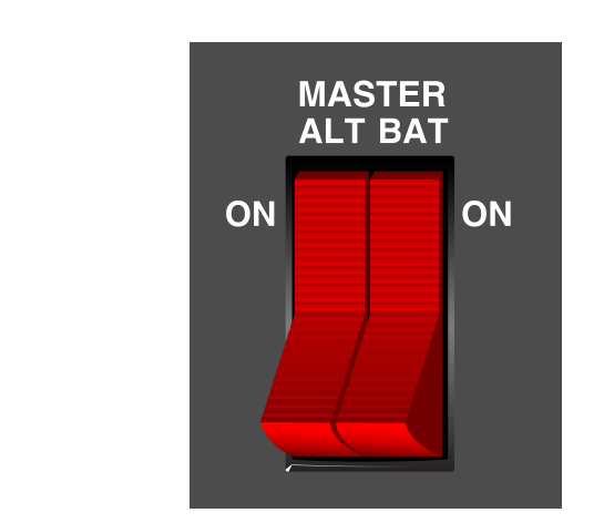
The master switch is the pilot's primary control over the aircraft's electrical system. In most single-engine trainers — such as the Cessna 172 — the master switch is a split rocker switch divided into two halves: an ALT (alternator) side and a BAT (battery) side. The physical left/right arrangement of these two halves varies by aircraft installation and is not a standardized FAA specification, so always confirm the layout in the specific aircraft's POH. Understanding each half is essential.
BAT Side
Turning on the BAT side connects the battery to the main bus bar, energizing all electrical circuits. Common guidance calls for turning the BAT side on before the ALT side during startup, and the ALT side off before the BAT side during shutdown, to help avoid a voltage spike that could damage avionics when the alternator field collapses — but the exact sequencing is aircraft-specific and governed by the POH rather than a universal FAA rule.
ALT Side
The ALT side controls the alternator field circuit — essentially switching the alternator's ability to generate electricity on or off. It does not disconnect the alternator physically; it controls the excitation current that makes the alternator function. Turning off the ALT side while the BAT is on leaves the battery as the sole power source — exactly the situation you would face after an in-flight alternator failure.
Correct Sequencing
The correct procedure varies by aircraft: some POHs call for turning both sides ON together (or BAT first, then ALT) before starting, and on shutdown turning the ALT side OFF first, then the BAT side, while others specify both together. Always defer to the aircraft's specific Pilot's Operating Handbook (POH) for the exact checklist sequence, because procedures can vary. The reasoning commonly given for a staggered shutdown sequence is that cutting the ALT field before the BAT can help avoid an instantaneous voltage transient that could harm the avionics bus — but this is POH-specific guidance rather than a universal FAA rule.
Monitoring: Ammeter vs. Loadmeter
Two types of instruments can tell you what the electrical system is doing in flight, and the FAA exam often asks you to interpret their readings:
- Ammeter (charge/discharge type): This instrument is wired between the battery and the bus bar. A positive (charge) reading means the alternator is producing more power than the system is consuming, and the surplus is charging the battery — normal during cruise. A negative (discharge) reading means the battery is supplying power to the bus, indicating the alternator has failed or is not keeping up with demand. A discharge reading in flight should prompt immediate troubleshooting.
- Loadmeter (alternator output type): This instrument shows how much current the alternator is actually producing at any given moment, as a percentage of rated capacity or in amperes. A sudden drop to zero on a loadmeter indicates the alternator has stopped producing power, signaling a failure even if the battery is maintaining voltage momentarily.
Some aircraft have a low-voltage warning light instead of or in addition to these gauges. A low-voltage light illuminating in flight is a clear signal to check the alternator and manage your electrical load immediately.
Why It Matters: Safety and Airmanship
Electrical failures in flight are more common than many student pilots expect, and the consequences vary from a dark cockpit to a complete loss of navigation capability in IMC. Understanding your system empowers you to act quickly and correctly. For example: if your ammeter shows a persistent discharge in cruise, resetting the ALT side of the master switch may restore the alternator (some alternators trip off due to a momentary overvoltage). If the alternator will not reset, you must reduce electrical load immediately — turn off non-essential lights, unneeded radios, and electric fuel pumps — then plan to land at the nearest suitable airport before the battery is depleted. Knowing your battery's approximate endurance is part of sound pre-flight risk management.
Additionally, leaving the master switch on after shutdown drains the battery, potentially leaving you with a dead battery at the next preflight. This is a frequent cause of delayed departures and is also a ground-safety issue, since keeping the master on can power the fuel pump or produce sparks near the exhaust.
Key Numbers and Rules
- 14-volt system: Standard in most single-engine trainers; battery is nominally 12 V, alternator output regulated to exceed battery voltage by a small margin (exact figure varies by aircraft and regulator).
- 28-volt system: Common in twins and more complex singles; battery is nominally 24 V.
- Circuit breakers vs. fuses: Circuit breaker reset guidance is aircraft- and POH-specific — some POHs permit a single reset attempt if a breaker trips, while others prohibit resetting certain breakers in flight at all; fuses must be replaced. Always follow the specific POH guidance.
- Battery endurance after alternator failure: Not a fixed, FAA-published figure; it varies greatly by battery condition and loads active — always shed nonessential equipment immediately.
- Alternator vs. generator: Alternators are more efficient at low RPM and are standard on modern GA aircraft; generators were common on older aircraft and produce less current at idle.
- Master switch OFF on shutdown: Leaving the master ON drains the battery and can be a fire or safety hazard on the ground.