When an aircraft control surface — aileron, elevator, or rudder — vibrates rapidly and uncontrollably at certain airspeeds, the result is called flutter. Flutter is not a nuisance; it is a catastrophic structural failure mode that can destroy an aircraft in seconds. To prevent it, designers use two closely related but distinct engineering strategies: mass balancing and aerodynamic balancing. Aviation maintenance technicians (AMTs) working on airframe flight control systems must thoroughly understand both concepts, because improper repairs, unauthorized paint applications, or failure to restore original balance after component replacement can upset the designed balance state and create a flutter hazard.
This article explains the physics behind flutter, how each balancing method counters it, the specific hardware forms each method takes, and what an AMT must watch for during inspection and repair. The content is grounded in the FAA Airframe Mechanic knowledge base as described in the Aviation Maintenance Technician Handbook — Airframe (FAA-H-8083-31).
Understanding Flutter: Why Balance Is Necessary
A control surface is hinged along one edge (the hinge line) and free to rotate. At high airspeeds, aerodynamic forces acting on the surface can couple with the natural structural flexing of the wing or tail to create an oscillating feedback loop. Each oscillation adds energy to the next, and the amplitude grows exponentially — this is flutter. The two primary factors that determine whether flutter occurs are airspeed and the relationship between the surface's center of gravity (CG) and its hinge line.
If the surface's mass CG is located behind the hinge line — which is the natural condition for most unbalanced surfaces, because the bulk of the surface area and structure trails aft — the surface is inherently susceptible to flutter. When the wing flexes upward, inertia causes the trailing surface to lag behind, deflecting it downward. That deflection changes the local aerodynamic force, which then drives further motion. Mass balancing and aerodynamic balancing each attack this problem from a different angle.
Mass Balancing
The Principle
Mass balancing moves the control surface's overall CG to the hinge line, or even slightly ahead of it. When the CG is at or forward of the hinge, inertia no longer drives the surface away from neutral during a structural oscillation — instead, inertia resists the deflection, breaking the feedback loop and preventing flutter from building.
Hardware Forms
The most common hardware implementation is a balance weight — a lead or tungsten weight attached to an arm that projects forward of the hinge line. You will see these on ailerons as a counterweight running spanwise ahead of the hinge, and on elevator and rudder surfaces as horn-style projections or internal weights mounted forward. Some aircraft use internally buried weights sealed within the leading edge of the surface itself.
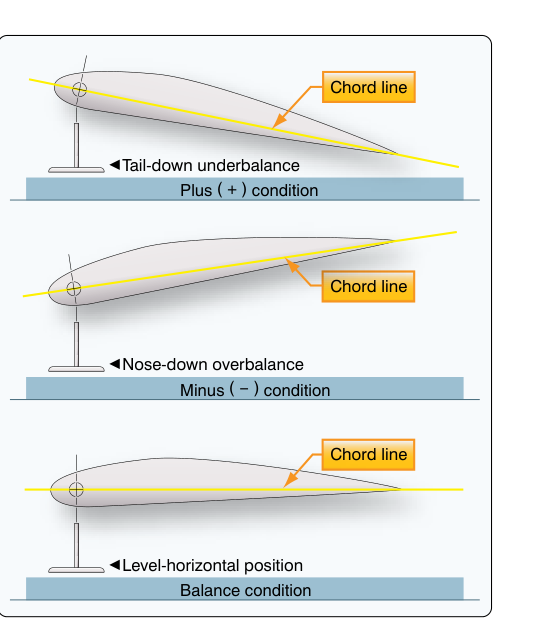
The precise amount of mass and its distance from the hinge (the moment arm) are calculated during the original design and certified as part of the type design. The FAA-H-8083-31 handbook describes the process of control surface balance checking, where the surface is removed, placed on a balance fixture or knife-edge stand at the hinge points, and allowed to rotate freely. The resulting movement — nose-heavy (forward CG), tail-heavy (aft CG), or neutral — is compared against the aircraft manufacturer's specified limits as documented in the maintenance manual or service instructions.
Maintenance Implications
Any action that adds weight to a control surface can shift its CG aft and reduce or eliminate the designed balance margin. The most common culprits include:
- Paint: Even a single extra coat of paint applied to the aft portion of a surface adds ounces of weight behind the hinge line. The FAA-H-8083-31 explicitly notes that refinishing a control surface without rebalancing afterward is a known flutter hazard.
- Repairs: Fabric patches, bonded doublers, or replacement skin panels that add material aft of the hinge can shift CG.
- Replacement balance weights: If a weight is damaged or removed and not correctly restored to manufacturer specification, the surface may no longer meet balance requirements.
- Moisture and contamination: Water, dirt, or ice trapped inside a fabric or hollow metal surface adds uncontrolled weight at an unknown location.
After any repair or refinishing, the AMT must re-check the surface balance per the manufacturer's procedure and restore it to the specified range — either by adding approved balance weight or, where permitted, by removing material from the appropriate location. Only manufacturer-approved methods may be used; improvisation is not acceptable on certified aircraft.
Aerodynamic Balancing
The Principle
Aerodynamic balancing reduces the hinge moment — the aerodynamic force that resists control surface deflection and is felt by the pilot as control force or stick force. Unlike mass balancing, which is primarily a flutter-prevention strategy, aerodynamic balancing also directly affects handling qualities and pilot workload. By cleverly shaping or positioning the control surface relative to the hinge line, designers can use the airstream itself to partially move or hold the surface, reducing the effort the pilot must apply through the control system.
Hardware Forms
Several distinct aerodynamic balance designs exist, and the AMT must recognize each:
- Horn balance (unshielded): A portion of the control surface area projects forward of the hinge line, typically at the tip. When the surface deflects, aerodynamic pressure on the forward horn creates a moment that assists the deflection, reducing pilot effort. The unshielded horn is exposed to the freestream on all sides.
- Shielded horn balance: Similar to the unshielded horn, but the projecting area is partially hidden behind the fixed surface (fin or stabilizer). This reduces the tendency of the horn to generate excessive flutter-inducing forces at high speeds and is a common design on general aviation rudders and elevators.
- Internal balance (sealed internal balance): A forward extension of the surface projects into a sealed chamber within the fixed surface. Pressure differentials between the upper and lower surfaces of this internal tab act on the extended area and help move the surface. This design is very clean aerodynamically and common on higher-performance aircraft.
- Overhang balance (set-back hinge): The hinge line is moved aft of the surface's leading edge, so a portion of the surface leading edge is forward of the hinge. This overhang area reduces hinge moment and is widely used on ailerons.
- Balance tabs (and anti-balance tabs): A small tab on the trailing edge of the control surface that deflects opposite to the main surface when it moves. The aerodynamic force on the tab assists in moving the main surface. Note that an anti-balance tab deflects in the same direction as the surface, deliberately increasing hinge moment so that stick force increases with the amount of surface deflection — used on some stabilator designs.
Maintenance Implications
Aerodynamic balance features are sensitive to surface contour. Damage that alters the shape of a horn balance, changes the gap between a balance tab and the main surface, or compromises the seal of an internal balance chamber will alter hinge moments in ways that can degrade handling or contribute to flutter. AMTs must inspect these areas carefully for corrosion, deformation, and correct gap/seal condition per the aircraft maintenance manual.
Why It Matters: Safety and Airworthiness
Flutter onset can occur within the normal operating envelope if balance is compromised. Certification standards (14 CFR 23.629 and 25.629) require the aircraft to be free from flutter up to a speed margin above VD (design dive speed) when the aircraft is in its certified condition. Any reduction in the balance margin erodes that certified margin. In extreme cases, improperly repaired or refinished control surfaces have led to in-flight structural failures. This is why 14 CFR Part 43 requires maintenance to return an aircraft to its original or properly altered condition, and why manufacturers specify control surface balance in Airworthiness Limitations or maintenance manual procedures.
Key Numbers and Rules
- Control surface CG must be at or forward of the hinge line to be flutter-resistant; specifications vary by aircraft model and are found in the maintenance manual.
- Balance is checked on a knife-edge fixture or balance stand at the manufacturer-specified hinge points — never estimated visually.
- Any control surface repair or refinishing requires a post-work balance check before return to service.
- Only manufacturer-approved balance weight material and attachment methods may be used — substituting denser or lighter material at a different location changes the moment and may not meet the type design.
- 14 CFR Part 43, Appendix D lists general items such as inspecting control system components for damage, wear, security, and proper operation as part of the annual/100-hour inspection scope; it does not itemize a specific mass or aerodynamic balance check, which is instead governed by the aircraft manufacturer's maintenance manual and Airworthiness Limitations.
- Balance limits are expressed as an allowable range of CG position (e.g., a manufacturer-specified distance forward of the hinge line) or as an allowable torque value on the balance fixture — the exact figures vary by aircraft type, so always consult the specific aircraft documentation.
Common Test Traps
- Confusing mass balance with aerodynamic balance: Mass balance prevents flutter by repositioning the CG. Aerodynamic balance reduces pilot control forces by using airstream pressure. They are different techniques, though some hardware (a forward horn) can contribute to both simultaneously.
- Assuming paint does not matter: Extra paint coats can shift the surface CG enough to fail balance limits. Always recheck balance after refinishing.
- Mixing up balance tab vs. anti-balance tab: A balance tab moves opposite to the surface and reduces control force; an anti-balance tab moves with the surface and increases control force. The stabilator anti-balance tab is a classic test question.
- Thinking any weight will substitute for the original: Balance weight must match the manufacturer's mass, material, and location specification exactly. A heavier weight placed closer to the hinge may produce the same moment, but is not an approved substitution without engineering data.
- Forgetting to check balance after fabric repairs: A fabric patch on the aft portion of a control surface adds ounces behind the hinge — enough to matter on lightweight surfaces. The post-repair balance check is a required step, not optional.