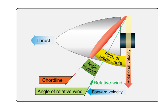
A propeller is, at its heart, a rotating wing. Every principle that makes an airplane wing generate lift applies equally to propeller blades — the same Bernoulli effect, the same angle-of-attack sensitivity, and the same risk of stalling. Understanding how propeller blades generate thrust is essential not only for passing the FAA Airframe and Powerplant (A&P) knowledge test, but also for making sound maintenance decisions that directly affect flight safety. This article examines the aerodynamic forces acting on a spinning propeller blade, how those forces combine to produce thrust, and the variables that govern how effectively a propeller does its job.
Before diving into specifics, it helps to think of the propeller as a device that translates rotary motion — delivered by the engine — into linear motion in the form of thrust. The blade achieves this by accelerating a mass of air rearward, following Newton's third law: every action (accelerating air rearward) produces an equal and opposite reaction (propelling the aircraft forward). But the mechanism by which the blade accelerates that air is purely aerodynamic, and understanding that mechanism is what separates the technician who simply replaces propellers from the one who truly understands them.
Blade Geometry: The Foundation of Force Production
A propeller blade has an airfoil cross-section, meaning it has a curved forward surface (the cambered face, also called the thrust face or front face) and a flatter aft surface (commonly called the blade back or flat face). As the blade rotates, it slices through the air much like a wing moves through it during flight. The blade is twisted along its length — a geometric feature called pitch twist — so that each section of the blade, from hub to tip, presents roughly the same effective angle of attack to the oncoming air despite the fact that tip sections travel at a much higher velocity than root sections.
The blade angle (also called the pitch angle) is measured between the chord line of the blade at a given station and the plane of rotation. By convention, blade angle is typically measured at a reference station 75% of the propeller's radius from the hub, because that station represents an average of the forces acting across the whole blade. A higher blade angle means the blade is more nearly parallel to the aircraft's direction of travel; a lower blade angle means the blade is more nearly perpendicular to it. This distinction becomes critical when understanding fixed-pitch versus variable-pitch propellers.
How Thrust Is Produced: Aerodynamic Lift Turned Forward
When the propeller rotates, each blade section experiences a relative wind that is the vector sum of two components: the rotational velocity of that blade section (tangential, in the plane of rotation) and the forward velocity of the aircraft (axial, along the thrust axis). The angle between this combined relative wind and the blade chord line is the blade angle of attack. As long as the blade angle of attack is positive and below the stalling angle, the blade produces an aerodynamic lift force — just as a wing does.
Here is the key insight: this aerodynamic lift force on the blade is not pointed straight upward as it is on a wing. Instead, because the blade is oriented in the plane of rotation, its lift vector is tilted mostly forward (along the direction of flight). That forward-pointing component of the lift force is thrust. There is also a component of the lift force acting in the plane of rotation, opposing the rotation of the blade — this is the aerodynamic source of propeller torque, the rotational resistance the engine must overcome to keep the propeller spinning.
In addition to lift, the blade also generates drag — both induced drag (a byproduct of lift production) and profile drag (skin friction and form drag). These drag forces also resolve into components: a rearward component that subtracts from thrust and an in-plane component that further resists rotation. The net forward force remaining after accounting for all these drag components is the usable thrust the propeller delivers to the airframe.
Factors That Control Thrust Output
Rotational Speed (RPM)
Higher RPM increases the rotational velocity of every blade section, which in turn increases the magnitude of the relative wind and the total aerodynamic force the blade can generate. Doubling RPM roughly quadruples the dynamic pressure on the blade (since dynamic pressure varies with the square of velocity), dramatically increasing potential thrust — up to the point where the blade tips approach the speed of sound and compressibility effects introduce efficiency losses.
Blade Angle and Pitch
Changing the blade angle changes the angle of attack that the blade presents to the relative wind for a given airspeed and RPM combination. In a fixed-pitch propeller, the blade angle is set at manufacture for a compromise between climb performance (lower pitch, higher RPM, more thrust at low airspeed) and cruise performance (higher pitch, more efficient at higher airspeeds). In a variable-pitch (controllable-pitch) propeller, the pilot or governor adjusts blade angle in flight to maintain the optimum angle of attack across a range of flight conditions, much like an automobile transmission keeps the engine in its power band.
Aircraft Forward Velocity
As the aircraft accelerates forward, the axial component of the relative wind increases. If blade angle is fixed, this increase in axial velocity effectively reduces the blade's angle of attack — and therefore reduces thrust. This is why a fixed-pitch propeller produces maximum thrust at the start of the takeoff roll (low forward speed, high angle of attack) and progressively less thrust as speed builds. The propeller efficiency (the ratio of useful power output, i.e., thrust times airspeed, to the engine shaft power input) typically peaks at a specific design airspeed and falls off on either side of it.
Air Density
Propeller thrust depends directly on the mass of air accelerated rearward per unit time. At high altitude or on hot days, air density decreases, so even though the blade moves through the same volume of air, it accelerates less mass. The result is reduced thrust for any given RPM and blade angle. This is the aerodynamic reason — separate from the engine's own power loss at altitude — why aircraft performance decreases in low-density air.
Propeller Efficiency and Slip
Propeller slip is the difference between the theoretical distance the propeller should advance per revolution (the geometric pitch) and the actual distance it advances (the effective pitch). Slip is not waste — it represents the angle of attack the blade needs in order to generate lift and therefore thrust. A propeller with zero slip would have zero angle of attack and produce no thrust at all. The goal of propeller design is not to eliminate slip but to minimize the energy lost to drag while maintaining sufficient slip (angle of attack) for the required thrust. Efficiency values for well-designed propellers typically range from about 75% to 90% at cruise conditions.
Why This Matters for Maintenance Technicians
Every aspect of blade aerodynamics is sensitive to the physical condition of the blade surface. A nick, gouge, or corrosion pit on the leading edge disrupts laminar airflow exactly as it would on a wing, reducing lift and increasing drag — degrading both thrust and efficiency. Even a seemingly minor surface defect can create a stress concentration that leads to fatigue cracking. This is why FAA regulations and manufacturer service manuals specify precise limits on blade damage, and why an A&P technician must carefully evaluate any blade damage against those limits before returning a propeller to service.
Blade angle settings are equally critical. Blade track (whether each blade tip follows the same path, or plane, of rotation) and blade angle (pitch) balance (whether all blades are set to the same pitch angle) are two distinct maintenance checks; if either is out of tolerance on a multi-blade propeller, asymmetric thrust and vibration result — both a performance and a structural concern. Proper blade angle verification with calibrated tools at the reference station is a standard maintenance task that directly affects the aerodynamic forces the propeller produces.
Key Numbers and Rules
- Reference station for blade angle measurement: 75% of the propeller radius from the hub (per FAA standard practice).
- Geometric pitch: the theoretical advance per revolution based on blade angle alone; effective pitch: the actual advance per revolution in service — always less than geometric pitch due to slip.
- Thrust face: the cambered (curved) side of the blade, facing forward (toward the engine); generates the lift force that produces thrust.
- Propeller efficiency range: typically 75–90% at design cruise conditions for well-maintained propellers.
- High-pitch propeller: large blade angle, suited to high-speed cruise; low-pitch propeller: small blade angle, suited to takeoff and climb.
- Blade angle of attack increases as aircraft forward speed decreases (and/or as RPM increases); blade will stall if angle of attack exceeds the critical angle.
- Propeller slip is necessary for thrust production — zero slip equals zero thrust.
Common Test Traps
- Confusing blade angle with angle of attack: Blade angle is a fixed geometric measurement from the chord line to the plane of rotation; angle of attack is the dynamic angle between the chord line and the actual relative wind, which changes with airspeed and RPM.
- Thinking higher pitch always means more thrust: At low airspeeds (takeoff, climb), a high-pitch blade presents too low an angle of attack to the relative wind and produces less thrust than a lower-pitch blade at the same RPM.
- Confusing the thrust face with the back of the blade: The thrust face is the cambered (curved) forward-facing side — the side facing the engine. Some students mistakenly identify the flat back as the thrust-producing face.
- Assuming slip is always bad: Propeller slip is essential — it is what gives the blade its angle of attack. Eliminating slip would eliminate thrust. The test may present slip as purely a loss to trick you.
- Ignoring density altitude's effect on thrust: Low density air reduces propeller thrust independently of engine power loss. Both factors combine to severely limit performance on hot, high-altitude days.