Every operating piston and turbine powerplant depends on a precise, continuous supply of fuel. Knowing exactly how much fuel the engine is consuming at any given moment is not merely a convenience — it is a fundamental safety requirement. Too rich a mixture wastes fuel and can foul spark plugs; too lean a mixture can lead to overheating and detonation, particularly at high power settings, or a flameout in turbine powerplants. The fuel flow indicating system bridges the gap between the fuel system and the flight deck, giving pilots and maintenance technicians a real-time window into the engine's fuel appetite. Two dominant technologies accomplish this task: the pressure-type fuel flow indicator, common on carbureted and simple fuel-injected piston engines, and the mass flow meter, the precision standard for turbine-powered aircraft. Understanding how each system works, why they differ, and where each one can mislead you is essential knowledge for any AMT pursuing a Powerplant certificate.
The Pressure-Type Fuel Flow System
The pressure-type system does not directly measure how much fuel is flowing. Instead, it infers flow rate by measuring fuel pressure at a specific point in the fuel delivery path. The underlying engineering logic is straightforward: for a given fuel-metering device and a fixed orifice size, pressure and flow rate are closely related. As the engine demands more fuel, the flow increases, and the pressure at the sensing point rises proportionally. A calibrated gauge translates that pressure reading into a flow indication, typically expressed in gallons per hour (GPH) on piston aircraft.
Components and Signal Path
In a carbureted system, the sensing line taps into the fuel inlet pressure upstream of the carburetor's main metering jet. In a continuous-flow fuel-injection system — such as the Lycoming or Continental designs common on general aviation piston engines — the sensing line is typically plumbed to measure the differential pressure across the injector nozzles or the fuel manifold pressure. A small-diameter vapor-elimination line and a restrictor are usually incorporated to protect the cockpit instrument from fuel surge and vapor lock. The instrument itself is a simple pressure gauge with a face calibrated in GPH rather than PSI, making the reading immediately meaningful to the pilot without any mental conversion.
Because the pressure-type system relies on mechanical pressure lines routed to the cockpit, it is important that maintenance technicians inspect these lines for chafing, security, and freedom from moisture traps. Moisture in the line can freeze at altitude, giving a falsely low or zero reading. A blockage or restriction in the sensing line will typically cause a low or fluctuating indication that does not accurately reflect actual fuel consumption; technicians should not assume a specific fault always produces a predictable high or low reading without inspecting the line.
The Mass Flow Meter
Mass flow meters represent a fundamentally different and more accurate approach. Rather than inferring flow from pressure, a mass flow meter directly measures the mass of fuel passing through the sensor per unit of time, typically expressed in pounds per hour (PPH). This matters enormously because the energy content of fuel — and therefore its effect on combustion — is proportional to its mass, not its volume. A pound of jet fuel releases a specific quantity of heat energy regardless of whether the fuel is cold and dense or warm and slightly expanded. A volumetric or pressure-based reading would change slightly with temperature-induced density changes; a mass reading does not.
How Mass Flow is Measured
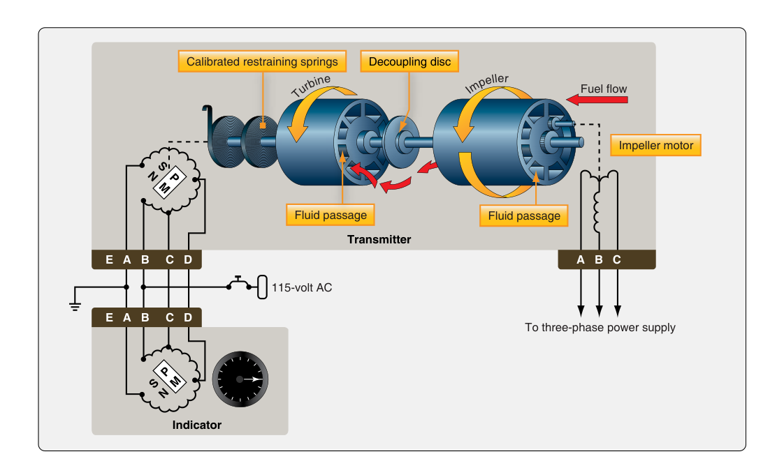
One widely used mass flow transducer design on turbine aircraft is the impeller-and-turbine type. Fuel enters a housing containing two rotating elements: a motor-driven impeller and a spring-restrained turbine. The impeller spins at a constant speed and imparts angular momentum to the fuel stream. The fuel then strikes the free-spinning turbine, causing it to rotate against the restraining force of a calibrated spring. The degree of angular displacement of the turbine — how far it rotates against the spring — is directly proportional to the mass flow rate of the fuel. A synchro or variable-reluctance pickup translates this angular displacement into an electrical signal, which drives a cockpit indicator calibrated in PPH or, on some installations, kilograms per hour.
A key advantage of this impeller-turbine design is its inherent compensation for fuel density changes. Because the measurement is based on momentum transfer (a mass-dependent phenomenon), denser fuel exerts more force on the turbine for the same volumetric flow, and less dense fuel exerts less — automatically correcting the reading without any additional temperature-compensation circuitry. This self-compensating behavior makes the mass flow meter highly accurate across a wide range of fuel temperatures and altitudes.
Turbine Engine Applications
On turbine-powered aircraft, mass flow meters are often paired with fuel totalizer systems. The totalizer integrates the flow signal over time to compute total fuel used since a reference point was set, giving the crew a running count of pounds consumed. Cross-checking the totalizer against known fuel loaded and the fuel quantity gauges is a standard preflight and in-flight verification procedure. Discrepancies between the totalizer and the quantity gauges can signal a fuel leak, a failed quantity probe, or a transducer error — each a serious maintenance concern that must be investigated before the next flight.
Why the Distinction Matters
The choice between pressure-type and mass flow measurement is not arbitrary — it reflects the operational and accuracy demands of the powerplant. Piston engines running on avgas tolerate the inherent imprecision of the pressure-type system because mixture control is relatively coarse and fuel density variations at piston-engine altitudes are modest. The pressure-type system is also simpler, lighter, and less expensive, making it a practical solution for a 180-horsepower trainer.
A turbofan burning thousands of pounds of fuel per hour on a transcontinental flight cannot afford such imprecision. Errors of even a few percent in fuel flow indication compound over a long flight into significant fuel-planning errors, with potentially catastrophic consequences. Mass flow meters offer substantially greater accuracy than pressure-type systems and are the preferred technology for these applications. They also interface cleanly with full-authority digital engine control (FADEC) systems and flight management computers (FMCs), which use the mass flow data for performance calculations, fuel prediction, and automatic engine management.
Key Numbers and Rules
- Pressure-type units: Gallons per hour (GPH); used primarily on piston aircraft with carbureted or continuous-flow fuel injection systems.
- Mass flow meter units: Pounds per hour (PPH) or kilograms per hour; used primarily on turbine-powered aircraft.
- Impeller-turbine transducer: Turbine deflection angle is proportional to mass flow rate — more mass flow equals greater angular displacement against the calibrated spring.
- Density compensation: Mass flow meters are inherently self-compensating for fuel density changes because they measure momentum, not volume.
- Common pressure-type fault — frozen or blocked sensing line: Produces falsely low, zero, or fluctuating indication in flight; caused by moisture accumulation at altitude or line restriction.
- Totalizer integration: On turbine aircraft, the mass flow signal is integrated over time to calculate total fuel consumed; used for cross-checking fuel quantity gauges.
- Accuracy standard: Mass flow meters are substantially more accurate than pressure-type systems across their operating range; the FAA Powerplant Handbook does not publish a specific percentage figure for this accuracy.
- Maintenance check: Pressure-type sensing lines must be purged of moisture and checked for chafing; mass flow transducers must be checked for correct calibration and secure electrical connections per the manufacturer's maintenance manual.
Common Test Traps
- Confusing the measurement parameter: The pressure-type system measures fuel pressure and converts it to an inferred flow reading — it does not directly measure flow. Students often incorrectly state that it measures actual flow volume.
- Units mix-up: Piston aircraft fuel flow is typically in GPH; turbine fuel flow is in PPH. Swapping these units on a test question will lead to wrong answers about system type and application.
- Mass flow meter principle: The exam may ask what physical property the impeller-turbine transducer actually measures. The answer is the angular displacement of the spring-restrained turbine, which corresponds to the momentum (and thus mass) of the fuel — not its pressure or velocity alone.
- Density compensation: A common distractor is suggesting that mass flow meters require external temperature sensors to compensate for density changes. In the impeller-turbine design, density compensation is automatic because momentum transfer is inherently mass-dependent.
- Fault interpretation: A blocked or restricted pressure-type sensing line typically causes a low or fluctuating fuel flow indication even if fuel is flowing normally. Maintenance technicians must recognize that an abnormal reading is not always an engine problem — it may be an instrument system fault, and the two must be systematically differentiated.