Every aircraft that flies under a pilot's command responds to control inputs through a carefully engineered system of movable surfaces. The three primary flight control surfaces — ailerons, elevators, and rudder — are the heart of this system. Each surface deflects into the airflow, generating aerodynamic forces that rotate the aircraft around one of its three principal axes. Understanding how each surface works, why it is shaped and positioned the way it is, and how the surfaces interact gives an aviation maintenance technician (AMT) the foundation needed to inspect, repair, and certify these safety-critical components correctly.
This article covers the structure, function, and common maintenance considerations for all three primary controls, grounded in the principles found in the FAA's Airframe and Powerplant handbooks and the Pilot's Handbook of Aeronautical Knowledge (FAA-H-8083-25).
The Three Axes of Flight
Before examining each surface individually, it helps to anchor them to the axes they control. An aircraft rotates around three mutually perpendicular axes, all of which pass through the aircraft's center of gravity (CG):
- Longitudinal axis — runs nose to tail; rotation around this axis is called roll, controlled by the ailerons.
- Lateral axis — runs wingtip to wingtip; rotation around this axis is called pitch, controlled by the elevator (or stabilator).
- Vertical axis — runs from top to bottom through the CG; rotation around this axis is called yaw, controlled by the rudder.
Each primary control surface works by changing the camber — and therefore the lift and drag — of the surface it is attached to, causing a rotational moment about the appropriate axis. The pilot's control inputs move these surfaces through a mechanical, cable-and-pulley, or fly-by-wire system, and the AMT's job is to ensure those systems remain airworthy.
Ailerons: Roll Control
Ailerons are hinged control surfaces located near the outboard trailing edge of each wing. They work as a pair in differential motion: when the pilot moves the control wheel (or stick) to the left, the left aileron deflects upward and the right aileron deflects downward simultaneously. The upward-deflected aileron reduces the camber of the left wing, generating less lift; the downward-deflected aileron increases the camber of the right wing, generating more lift. The resulting lift imbalance rolls the aircraft to the left, with the left wing dropping and the right wing rising.
The outboard placement of ailerons maximizes their mechanical advantage (moment arm from the aircraft's longitudinal axis), but this location also puts them in the region most susceptible to wing flex and flutter at high speeds. For this reason, many high-performance aircraft add inboard or high-speed ailerons that are used at cruise, while the outboard ailerons are locked or operate only at lower speeds.
Adverse Yaw
A critical side effect of aileron deflection is adverse yaw. The downward aileron creates more lift but also more induced drag on that wing, which tends to yaw the aircraft's nose toward the rising wing — the opposite of the intended turn direction. Engineers address this in several ways:
- Differential ailerons: the upward-deflected aileron travels through a greater arc than the downward-deflected aileron, equalizing drag on both sides.
- Frise ailerons: the leading edge of the upward aileron protrudes below the wing's lower surface, creating parasite drag on the low-lift (rising) side to balance the induced drag on the high-lift side.
- Coupled controls: rudder and aileron inputs are coordinated (either by the pilot or mechanically) to counteract the yaw.
Aileron Structural Considerations for the AMT
Ailerons are typically constructed as a light aluminum (or composite) structure hinged at two or more points along the rear spar. The AMT must inspect hinge bearings for wear and correct torque, check control cables and pushrods for proper tension and freedom from corrosion, verify that balance weights (used to prevent flutter) are secure and undamaged, and confirm that travel limits and rigging match the aircraft's maintenance manual specifications. Incorrect aileron rigging can cause the aircraft to fly with a wing-heavy condition or, in extreme cases, introduce flutter — a potentially catastrophic vibration.
Elevators: Pitch Control
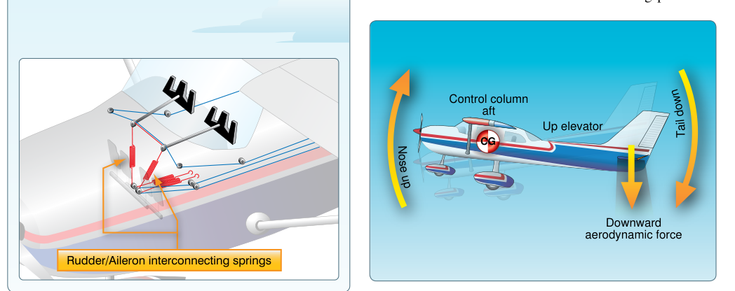
The elevator is a hinged surface attached to the trailing edge of the horizontal stabilizer at the tail of the aircraft. When the pilot pulls back on the control column, the elevator deflects upward, increasing the downward force (negative lift) on the tail. This force rotates the nose upward around the lateral axis, increasing the aircraft's pitch attitude. Pushing forward deflects the elevator downward, reducing the tail's downforce and pitching the nose down.
It is important to distinguish between pitch attitude and climb or descent: the elevator changes angle of attack and pitch attitude, but whether the aircraft climbs depends primarily on whether there is sufficient thrust and airspeed. This distinction is tested frequently on FAA knowledge exams.
Stabilators and Anti-Servo Tabs
Some aircraft (notably certain Piper models) replace the conventional fixed stabilizer/movable elevator combination with an all-moving horizontal tail called a stabilator. Because the entire surface moves, stabilators are very sensitive to small inputs. To reduce this sensitivity and provide the pilot with natural control feel, an anti-servo tab is installed on the trailing edge. Unlike a conventional trim tab that moves opposite to the control surface to reduce pilot effort, the anti-servo tab moves in the same direction as the stabilator, creating an aerodynamic force that resists the movement and improves control feel.
Elevator Structural Considerations for the AMT
The AMT must verify that elevator hinge points are secure and properly lubricated, inspect pushrod or cable systems for correct tension per the maintenance manual, and confirm that up and down travel limits are correct. Elevator balance is critical: if the elevator is not properly mass-balanced, it can flutter at high airspeeds. After any repair to an elevator surface — including painting — rebalancing must be performed in accordance with the manufacturer's data.
Rudder: Yaw Control
The rudder is a hinged surface on the trailing edge of the vertical stabilizer (vertical fin). When the pilot presses the left rudder pedal, the rudder deflects to the left, increasing the aerodynamic force pushing the tail to the right, which yaws the aircraft's nose to the left around the vertical axis. Right rudder pedal input has the opposite effect.
The rudder does not bank the aircraft in normal operation — that is the aileron's job. The rudder is used to coordinate turns (counteracting adverse yaw), to maintain directional control during crosswind takeoffs and landings, and to perform slips. In multi-engine aircraft, the rudder is essential for maintaining directional control following an engine failure.
Rudder Structural Considerations for the AMT
Like the other primary surfaces, the rudder must be inspected for hinge wear, proper cable tension and routing, correct travel limits, and mass balance integrity. The AMT should also check the rudder stops — physical limits that prevent over-deflection — for security and correct position. On larger aircraft, the rudder may incorporate a rudder limiter or yaw damper system to prevent pilot-induced over-deflection at high speeds, and these systems require periodic functional checks.
Why Primary Controls Matter to the AMT
Primary flight controls are listed among the most safety-critical components on any aircraft. A failure or malfunction in a primary control system — whether caused by incorrect rigging, a missed crack during inspection, improper hardware installation, or overlooked wear — can result in loss of control. The FAA classifies control system components as life-limited or on-condition items depending on the design, and all work must be performed in accordance with the manufacturer's approved maintenance manual and 14 CFR Part 43.
Every inspection and repair must be properly documented in the aircraft maintenance records. Major repairs to primary control surfaces — including structural repairs to the surface skin or spar — typically require an FAA Form 337 and may require a Designated Engineering Representative (DER) approval if not covered by existing structural repair manuals.
Key Numbers and Rules
- Control surface travel limits are specified in the aircraft's Type Certificate Data Sheet (TCDS) and maintenance manual — there is no universal value; always reference the specific aircraft documentation.
- Cable tension tolerances are temperature-dependent; the maintenance manual provides a tension/temperature chart that must be used during rigging.
- After any primary control surface repair, the surface must be rebalanced and the control system re-rigged before return to service.
- All primary control system work is a preventive maintenance exclusion — it cannot be performed by an owner/operator under 14 CFR Part 43 Appendix A; it requires an appropriately rated AMT or repair station.
- Functional checks of the full range of motion (free and correct movement, no binding, correct direction) must be performed after any control system maintenance before the first flight.
Common Test Traps
- Aileron direction confusion: Remember that the aileron on the rising wing deflects down (increasing lift), while the aileron on the descending wing deflects up (reducing lift). The control input moves in the direction of desired roll.
- Adverse yaw mechanics: Frise ailerons add parasite drag on the up-aileron side; differential ailerons give the up-going aileron more travel. Mixing these up is a common error.
- Anti-servo vs. servo tab: A servo tab moves opposite to the surface to assist movement (reduces pilot effort); an anti-servo tab moves in the same direction as the surface to resist movement (increases feel). They are opposites in both motion and effect.
- Rudder vs. aileron function: The rudder controls yaw only — it does not directly cause the aircraft to bank. Confusing yaw and roll is a frequent beginner mistake and a test question favorite.
- Rebalancing after repair: Many students forget that any repair — including a repaint — that changes a control surface's weight distribution requires rebalancing before return to service to prevent flutter.