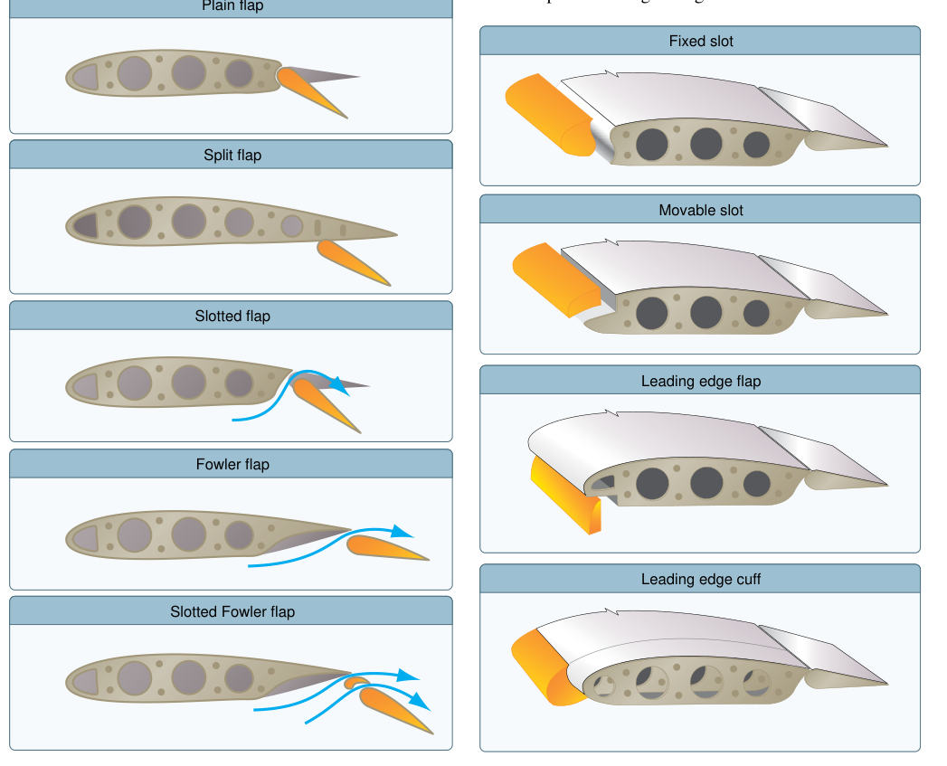
Wing flaps are among the most important high-lift devices found on modern aircraft. By temporarily altering the shape and area of the wing, flaps allow a pilot to fly at slower airspeeds without stalling, produce steeper approach angles without building excess speed, and reduce landing roll distance. For the AMT airframe technician, understanding how each flap type generates lift and drag — and how the mechanical systems that drive them are constructed and maintained — is fundamental to both the knowledge test and safe, airworthy maintenance practice.
Flaps are classified as secondary flight controls, meaning they augment the primary controls (ailerons, elevator, rudder) rather than replace them. They are typically mounted along the inboard trailing edge of the wing, though leading-edge devices serve a related purpose and are covered later in this article. Every flap installation must comply with the aircraft's Type Certificate Data Sheet (TCDS) and the manufacturer's maintenance manual, and any flap rigging, travel stop adjustment, or actuator replacement requires return-to-service in accordance with 14 CFR Part 43.
How Flaps Work: The Aerodynamic Principles
A wing generates lift by accelerating airflow over its upper surface, creating lower pressure above and relatively higher pressure below. The ratio of lift produced to the square of airspeed, wing area, and air density is captured in the lift equation: L = CL × ½ρV² × S. Flaps increase the lift coefficient (CL) by one or more of three mechanisms: increasing wing camber, increasing effective wing chord (and therefore area), and — in slotted designs — re-energizing the boundary layer to delay flow separation.
Increased camber accelerates airflow over the upper surface more aggressively, raising the pressure differential and thus lift at any given airspeed. This allows the aircraft to maintain level flight or a stable approach at a speed lower than it could achieve with a clean wing. Because the stall angle of attack is reached at a slightly lower geometric angle when flaps are deployed, pilots must be aware that the stall warning margin changes with flap setting. What flaps ultimately provide is a higher maximum CL, which translates directly into a lower stall speed (VS).
All flap types also introduce drag — some more than others. This drag is not simply a penalty; it is frequently desirable on approach because it allows a steeper glide path without a corresponding increase in airspeed. The ratio of lift to drag (L/D) decreases with increasing flap extension, which is exactly why full flaps are generally used for landing but not for normal cruise.
Types of Wing Flaps
Plain Flap
The plain flap (also called a simple or hinged flap) is the most basic design. It is formed by hinging the trailing portion of the wing so that it can rotate downward. When deflected, the mean camber line of the airfoil increases, raising CL. The plain flap is mechanically simple and easy to maintain, but it produces relatively high drag and tends to suffer from airflow separation on its upper surface at large deflection angles, limiting its aerodynamic effectiveness. It is commonly found on light general aviation aircraft and training airplanes.
Split Flap
The split flap deflects only the lower surface of the trailing edge downward, leaving the upper surface of the wing undisturbed. Because the upper surface geometry does not change, the split flap produces slightly less lift than a plain flap at the same deflection angle but generates considerably more drag. This makes it effective as a drag device for steepening approaches, but its high drag-to-lift ratio means it falls short of more sophisticated designs. Split flaps were common on aircraft of the 1930s–1950s and are rarely found on modern designs.
Slotted Flap
The slotted flap is one of the most widely used designs on contemporary light aircraft and regional airliners. When the flap moves aft and down, a slot — a carefully shaped gap — opens between the wing's main element and the flap. High-pressure air from beneath the wing flows through this slot and is directed across the upper surface of the flap. This re-energizes the boundary layer, preventing early airflow separation and allowing the flap to be deflected to much larger angles without stalling the flap surface. The result is a significantly higher CL than either plain or split flaps can achieve. Single-slotted flaps are widely used on modern piston singles and light twins, though plain and split flaps also remain common on many light aircraft designs.
Fowler Flap
The Fowler flap moves rearward as well as downward along a curved track or carriage system. This rearward movement increases the effective chord of the wing and therefore the total wing area (S in the lift equation), while the downward component increases camber. The combined effect produces the highest increase in maximum CL of any single-element flap type. Fowler flaps are commonly slotted as well, giving them boundary-layer re-energization on top of their area-increasing benefit. They are standard equipment on most transport-category aircraft, turboprops, and many high-performance piston aircraft. The mechanical system — tracks, rollers, actuating screws or hydraulic actuators — is more complex and requires careful inspection for track wear, roller condition, and proper alignment during maintenance.
Double- and Triple-Slotted Flaps
High-performance transport aircraft often use double- or triple-slotted Fowler flaps, which divide the flap into two or three elements (the main flap, a vane or mid-flap, and an aft flap). Each element has its own slot, providing multiple stages of boundary-layer re-energization. This allows large flap deflections, with maximum angles varying considerably by aircraft type, and very high CL values. The mechanical complexity is substantial, and AMT technicians working on transport-category aircraft must be particularly attentive to the sequencing, synchronization, and load paths of these systems.
Leading-Edge Devices
Though not trailing-edge flaps, leading-edge high-lift devices are closely related and often tested together. Leading-edge slats are movable panels on the wing's leading edge that slide forward and down, opening a slot between the slat and the main wing. This slot directs energized air over the upper wing surface, dramatically delaying stall to much higher angles of attack. Leading-edge flaps (or droop-snoot leading edges) simply rotate the leading edge downward to increase camber. Krueger flaps fold out from the lower leading-edge surface. These devices are most common on large jet transports but appear on some high-performance piston and turboprop aircraft as well.
Flap Actuation Systems
Flap actuation systems fall into three broad categories. Manual systems, found on light aircraft, use a mechanical linkage — cables, push-pull rods, or a simple pivot handle — connected directly to the flap. The pilot supplies the actuating force. Electric systems use a reversible DC motor and jackscrew, worm gear, or torque tube arrangement to extend and retract the flaps. A flap position indicator and limit switches are critical components that must be verified during rigging. Hydraulic systems, standard on larger aircraft, use hydraulic actuators powered by the aircraft's hydraulic system. Synchronization between left and right flaps is critical: an asymmetric flap condition — where one side extends significantly more than the other — creates a powerful rolling moment that can be very difficult to counteract with aileron alone.
Why It Matters: Safety and Maintenance Implications
Flap system integrity is directly tied to aircraft safety. Asymmetric flap deployment has caused fatal accidents, which is why modern aircraft incorporate mechanical interconnects, torque tubes, or electronic monitoring to detect and limit asymmetry. AMT technicians must verify flap travel limits, up-stop and down-stop positions, correct rigging tension or jackscrew preload, and smooth operation throughout the full range of motion. Worn or binding tracks, cracked flap skins, corroded hinge pins, or improperly adjusted limit switches can all degrade flap performance or cause in-flight failures. Any discrepancy must be corrected and documented per 14 CFR Part 43 before the aircraft is returned to service.
Key Numbers and Rules
- Flap speed (VFE): The maximum airspeed at which flaps may be extended. Shown as the upper limit of the white arc on the airspeed indicator. Exceeding VFE risks structural damage to the flap and its hinges.
- White arc (airspeed indicator): Represents the full flap operating range — from VSO (stall speed, full flaps, landing configuration) at the bottom to VFE at the top.
- Effect on stall speed: Flap extension lowers stall speed because CL increases. Full flaps produce the lowest stall speed but also the highest drag.
- Fowler flap motion: Increases both camber AND wing area — the only single-element flap type that increases effective wing area, giving it the highest CL increase of any common trailing-edge design.
- Asymmetric flap limit: Acceptable flap asymmetry limits are aircraft-specific, defined by type design and the aircraft's TCDS/AFM rather than a universal number; beyond the approved limit, aileron authority may be insufficient to maintain wings-level flight.
- Maintenance authority: Flap rigging and repairs must be accomplished per the applicable maintenance manual and returned to service per 14 CFR Part 43, with an appropriate maintenance record entry.
Memory Aid
"Plain, Split, Slotted, Fowler — Each Flap Does More" — This sequence reflects increasing aerodynamic sophistication and CL generation:
- Plain: Camber only — simple hinge, moderate lift, high separation drag at large angles.
- Split: Lower surface only — more drag than lift, good approach drag device.
- Slotted: Slot re-energizes boundary layer — higher CL, less separation, very common.
- Fowler: Moves aft AND down — increases area AND camber, highest CL of trailing-edge types.
Common Test Traps
- Fowler vs. plain lift increase: Test questions often ask which flap type produces the greatest increase in CL. The answer is the Fowler (especially double- or triple-slotted Fowler), not the plain flap, because it increases both camber and wing area.
- Split flap drag: Students sometimes assume the split flap generates the most lift because it deflects the most. In fact, it generates more drag than lift compared to slotted designs — its strength is as a drag device.
- VFE vs. VA: VFE (top of the white arc) is the flap extension limit speed. VA is the maneuvering speed. These are different limits with different purposes; confusing them is a classic exam mistake.
- Slat vs. flap function: Leading-edge slats primarily delay stall to higher angles of attack by allowing smooth airflow to continue over the upper wing surface at higher angles of attack — they do not dramatically change approach angle the way trailing-edge flaps do. Know this distinction.
- Asymmetric flaps: If an exam question describes one flap extended and one retracted, the correct immediate concern is the rolling tendency and potential loss of lateral control — not simply an airspeed or drag issue.