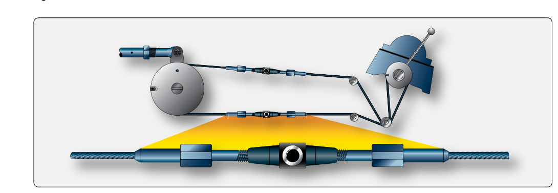
Most general aviation and transport-category aircraft rely on cable and pulley systems to connect the cockpit controls to the primary flight control surfaces — the ailerons, elevator, and rudder. These systems have been used since the earliest days of powered flight because they are lightweight, reliable, and capable of routing control inputs around structural members and through complex airframe geometry. For the airframe AMT, mastering cable and pulley systems means understanding not only how each component works, but also how to inspect, rig, and maintain them to the manufacturer's exact specifications.
Unlike push-pull tube systems, which work in compression and tension, cable systems work exclusively in tension. That single fact drives nearly every design and maintenance decision: cables must be kept properly taut, must not kink or corrode, and the entire routing must be free of interference so that tension — and nothing else — transmits the pilot's input faithfully to the control surface.
System Components and How They Work
A typical cable flight control system consists of several key components working together. Understanding each one individually is the foundation for competent maintenance.
Control Cables
Aircraft control cables are made from carbon steel or corrosion-resistant steel (CRES) wire strands twisted together into a finished cable. The most common constructions you will encounter are 7×7 and 7×19. A 7×7 cable has seven strands of seven wires each, giving 49 wires total; it is relatively stiff and is used for applications requiring low stretch and moderate flexibility. A 7×19 cable has seven strands of nineteen wires each, giving 133 wires total; it is more flexible and is preferred for applications with small-radius pulleys or frequent movement, such as primary flight controls. A third type, 1×19 (a single strand of 19 wires), is the stiffest and is used only for fixed or lightly-moved applications such as trim tab controls. Cable diameter is selected by the designer to handle the required loads with an appropriate safety factor; common sizes range from 1/16 inch to 3/8 inch diameter in primary systems.
Turnbuckles
Turnbuckles are threaded adjustment devices used to set and maintain proper cable tension. A standard turnbuckle has a barrel with right-hand threads on one end and left-hand threads on the other, accepting a cable terminal on each side. Rotating the barrel draws both terminals inward, increasing tension, or releases them to reduce tension. After adjustment, turnbuckles must be safety-locked to prevent inadvertent rotation. The two approved locking methods are the clip-locking method (using safety clips) and the wire-wrapping method (using lock wire). After locking, no more than three threads should be visible outside the barrel on either end — this is a standard inspection check point and a common test question. If more than three threads are exposed, the cable terminal may be close to pulling out of the barrel.
Pulleys
Pulleys change the direction of cable travel and allow the system to route around structural members. They are typically made from aluminum alloy or phenolic (plastic) material. Each pulley rotates on a bearing or bushing and is mounted on a bracket bolted to the airframe structure. Pulleys must be aligned so that the cable rides in the center of the groove without rubbing the pulley flanges or the guards. Cable guards are small pins or plates mounted close to the pulley that prevent the cable from jumping out of the groove if slack momentarily occurs. During inspection, the AMT checks pulleys for bearing roughness, flat spots on the rim caused by a jammed cable (a pulley defect, distinct from wear found on the cable itself), cracks, and proper alignment. A pulley that wobbles, spins rough, or shows flat spots must be replaced.
Fairleads
Where a cable passes through a bulkhead, rib, or other structure, a fairlead guides it and prevents chafing. Fairleads are made of phenolic, nylon, or soft aluminum and must contact no more than a very small arc of the cable circumference — they simply guide, they do not change cable direction. The maximum change in cable direction permitted through a fairlead is 3 degrees. If a larger direction change is needed, a pulley must be used instead. Fairleads that show excessive wear grooves must be replaced before they damage the cable.
Pressure Seals
On pressurized aircraft, cables passing through pressure bulkheads are routed through pressure seals. These seals allow cable movement while preventing pressurized air from escaping. They require periodic inspection for deterioration and proper seating.
Cable Tension and Rigging
Correct cable tension is one of the most critical rigging parameters. Too little tension allows cables to slacken, which can cause sloppy control feel, allow cables to jump pulleys, or even permit a cable to go slack enough to wrap around a structure. Too much tension overloads the cables, terminals, and airframe attachment points, causes excessive pulley and fairlead wear, and can actually restrict control surface travel. Tension is always measured with a cable tensiometer, a hand-held tool that deflects the cable a calibrated amount with a riser and reads the resulting force on a scale or dial. The reading must be corrected for cable diameter using a conversion chart that comes with the tensiometer.
Critically, cable tension changes with temperature because cables and airframe structures are made of different materials that expand and contract at different rates. Aluminum airframes expand more than steel cables when heated, which tends to slacken cable tension. Manufacturers publish tension ranges — not single values — and specify the temperature at which the measurement should be taken, or provide a temperature-compensation table. Always rig to the manufacturer's Aircraft Maintenance Manual (AMM) or aircraft specifications; using generic values is not acceptable.
After setting tension, the AMT must verify control surface travel using a protractor or travel board. Travel is checked in both directions and must fall within the manufacturer's specified range. If travel limits and tension limits cannot both be achieved simultaneously, something in the system is mis-rigged or a component is worn or damaged.
Cable Inspection Techniques
Cable inspection is a hands-on skill. The standard method is to wipe the cable clean and then run a cloth slowly along its full length while looking and feeling for broken wires. A broken wire will snag the cloth. The FAA and manufacturers establish rejection criteria based on the number of broken wires within a specified length. Guidance such as AC 43.13-1B addresses how many broken wires per lay length warrant replacement, and this number varies by cable construction and location on the cable — always defer to the manufacturer's specification, as some applications are more critical than others.
In addition to broken wires, inspect cables for corrosion (which appears as reddish-brown staining and pitting), kinking (a permanent bend that destroys the cable's strength and cannot be straightened), birdcaging (a bulging or unraveling of strands caused by a sudden shock load), and excessive wear at contact points with pulleys or fairleads. Cables showing any of these defects must be replaced — they cannot be repaired.
Cable Terminals and End Fittings
Cables are attached to turnbuckles, bellcranks, quadrants, and other fittings through end terminals. Common terminal types include the swaged terminal (a metal sleeve compressed hydraulically onto the cable end, providing the highest strength and cleanest installation), the Nicopress sleeve (a copper or aluminum sleeve pressed on with a special tool, used for field repairs and with reduced strength ratings), and the threaded clevis or fork terminal. Swaged terminals must be proof-tested and inspected for cracks at the swage and for corrosion. Proof testing is performed to a specified proof load defined by the swage tooling manufacturer or AMM data (commonly a percentage of cable rated strength well below the cable's ultimate breaking strength) rather than a fixed universal figure, and a terminal that fails this proof load must be replaced. Nicopress splices must be made with the correct number of presses and verified with a go/no-go gauge.
Why Cable System Integrity Matters
A failure anywhere in a cable flight control system can result in loss of control of a primary control surface. Unlike hydraulic or electrical systems that often have redundancy, a simple single-cable primary control system provides no backup. For this reason, 14 CFR Part 43, Appendix D requires that the flight control system be inspected for proper operation and condition at each annual or 100-hour inspection, and that any defect found be corrected before the aircraft is returned to service. Proper rigging also affects aircraft performance and handling qualities; an improperly rigged control system may mask adverse flight characteristics or cause asymmetric control response.
Key Numbers and Rules
- 7×7 cable: 49 wires total; semi-flexible, used for moderate-movement applications.
- 7×19 cable: 133 wires total; most flexible, preferred for primary flight controls with small-radius pulleys.
- 1×19 cable: 19 wires, single strand; stiffest, used for lightly-moved or fixed applications (e.g., trim).
- Turnbuckle thread exposure: No more than three threads visible outside the barrel after rigging.
- Fairlead direction change limit: Maximum 3 degrees. More than 3 degrees requires a pulley.
- Broken wire rejection standard: Number of broken wires per lay length that warrants replacement varies by cable type and location — always check the manufacturer's AMM or AC 43.13-1B for the applicable limit.
- Tension measurement tool: Cable tensiometer, corrected for cable diameter and temperature.
- Turnbuckle locking: Must be locked with approved safety clips or lock wire after every adjustment.
Common Test Traps
- 7×7 vs. 7×19 confusion: Students often mix up which cable type is more flexible. Remember: more wires per strand (19 vs. 7) means smaller individual wires, which means more flexibility. The 7×19 is the most flexible and is correct for primary flight control cables running over small pulleys.
- Fairlead vs. pulley: Test questions often ask which device is used when a cable must change direction by more than 3 degrees. The answer is a pulley — a fairlead is limited to 3 degrees of direction change.
- Turnbuckle thread rule: The three-thread rule is a classic test question. More than three exposed threads means the barrel has been adjusted too far and the terminal may be at risk of pulling through.
- Tension and temperature: A question may describe rising ambient temperature and ask what happens to cable tension. Because aluminum expands more than steel, tension typically decreases as temperature rises in an aluminum airframe. Rigging must account for this.
- Birdcaging: This defect — a bulging or splayed appearance of cable strands — is caused by sudden shock loading (such as a cable suddenly going slack and then snapping taut). A birdcaged cable must be replaced, never re-tightened and left in service.