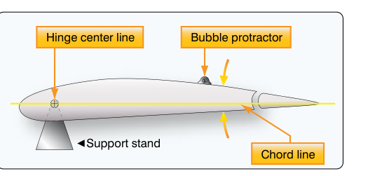
Every movable flight control surface on a certificated aircraft — ailerons, elevators, rudder, flaps, and trim tabs — must deflect through a precisely defined range of motion and return to a known reference position. These requirements are not suggestions or approximations; they are airworthiness standards published in each aircraft's maintenance manual, Type Certificate Data Sheet (TCDS), and the associated FAA-approved data. When an aircraft mechanic performs rigging checks, installs a new cable or pushrod, or reassembles a control system after a repair, verifying travel limits and confirming the neutral (faired) position of each surface is one of the most safety-critical steps in the entire process.
Understanding why these limits exist — and exactly how to verify them — is fundamental knowledge for any AMT airframe student preparing for the FAA knowledge test and, more importantly, for safe work in the field. This article walks through the mechanics of control surface geometry, the tools and methods used to measure travel and neutral point, the regulatory framework, and the practical traps that catch unprepared mechanics.
What Travel Limits and Neutral Point Mean
A travel limit is the maximum allowable angular deflection of a control surface from its neutral (faired) position, measured in degrees of arc. Most manufacturer data specifies both an up/down or left/right limit and a tolerance band — for example, an elevator might be specified with a value such as 25° ± 1° trailing-edge up and 20° ± 1° trailing-edge down as an illustrative example; actual limits vary by aircraft type and are found in the applicable TCDS or maintenance manual. The aircraft must fall within those tolerance bands; being outside them, even by a fraction of a degree beyond the tolerance, constitutes an out-of-rig condition that must be corrected before flight.
The neutral point — sometimes called the faired position or streamlined position — is the position in which the control surface creates the least aerodynamic disturbance and is geometrically aligned with the fixed surface to which it is attached. For a symmetrical airfoil section (which most control surfaces approximate), neutral position is the point where the trailing edge of the movable surface is in line with the trailing edge of the fixed surface, creating a smooth, continuous contour. A misrigged neutral point means the surface is pre-loaded in one direction at rest, introducing unintended aerodynamic forces even when the cockpit controls are centered.
How Control Surface Travel is Measured
The standard tool for measuring control surface deflection is the protractor or inclinometer, often called a rigging board or a bubble inclinometer. Some shops use a digital inclinometer for improved accuracy. The instrument measures the angle of the surface relative to a known reference — typically the chord plane of the fixed surface to which the movable surface is attached, or a specified waterline or fuselage reference station identified in the aircraft maintenance manual.
Step-by-Step Measurement Process
- Level the aircraft. Before any rigging measurement is meaningful, the aircraft must be placed in its specified level flight attitude using the manufacturer's leveling points. Many maintenance manuals require the aircraft to be leveled both laterally and longitudinally. An unlevel aircraft produces false angular readings on an inclinometer.
- Zero the instrument on the fixed reference. Place the inclinometer on the fixed surface (for example, the horizontal stabilizer for elevator measurement, or the vertical fin for rudder measurement) at the location specified in the manual, and zero or record the baseline angle. This baseline accounts for any built-in incidence or wash in the structure.
- Deflect the surface to its stop. Move the cockpit control — or the surface itself if directed — to the full-travel mechanical stop in one direction. The stop may be a hard stop in the control quadrant, a pushrod bottoming out, or a cable going taut at a turnbuckle. Record the angle shown on the inclinometer.
- Calculate net deflection. Subtract the baseline (neutral) reading from the full-deflection reading to obtain the net degrees of travel. Compare this figure to the value in the TCDS or maintenance manual, including the stated tolerance.
- Repeat in the opposite direction. Perform the same process for the opposing direction of travel. Unequal up and down (or left and right) deflections are normal for many aircraft; the manual will specify each direction separately.
- Verify neutral point. Return the cockpit control to its neutral position (or center it against a rigging fixture if provided). Place the inclinometer on the control surface. The reading should match the baseline taken on the fixed surface, confirming the surface is truly faired. A discrepancy indicates the cable tensions, pushrod lengths, or bellcrank geometry must be adjusted.
Establishing and Verifying the Neutral Point
Neutral point verification is more nuanced than it might appear. Many aircraft specify a rigging fixture — a block or template that physically spans the gap between the fixed and movable surface at a defined chord station and confirms the two trailing edges are flush. Others use alignment pins or drill-guide holes in bellcranks or control horns that must align when the surface is at neutral. When the manufacturer provides a physical fixture or pin alignment method, it takes precedence over inclinometer readings alone, because it is not subject to instrument calibration error.
For trim tabs, neutral point verification follows the same principle but uses the trim tab's own chord as the reference against the primary control surface's chord. A trim tab that is not faired at its mechanical neutral position will apply a steady aerodynamic moment to the primary surface, effectively pre-biasing it out of trail. This can manifest in flight as a persistent roll, pitch, or yaw tendency that the pilot must correct with sustained control input — a subtle but significant airworthiness concern.
It is also important to distinguish between geometric neutral (the surface is physically aligned) and aerodynamic neutral (the surface produces zero net moment). These are very close but not identical for most real-world airfoil shapes due to camber and thickness. Maintenance manuals are written around geometric neutral as defined by specific physical references; the aerodynamic effect is accounted for in the overall design. Mechanics work to the geometric specification.
Regulatory Framework and Approved Data
Under 14 CFR Part 43, any maintenance, preventive maintenance, or alteration must be performed in accordance with the methods, techniques, and practices prescribed in the manufacturer's current maintenance manual or Instructions for Continued Airworthiness (ICA), or other methods approved by the FAA Administrator. For certificated type-designed aircraft, control surface travel limits are part of the approved type design and appear in the TCDS. Deviating from TCDS-specified travel limits — even unintentionally — may render the aircraft unairworthy and could constitute a return-to-service violation under 14 CFR Part 43. Appendix D to Part 43 describes the scope and detail of items to be examined during annual and 100-hour inspections generally, including flight control systems, but it does not itself designate any item as a Required Inspection Item (RII); the RII concept and requirement are established separately for air carrier maintenance programs under 14 CFR 121.371 and 14 CFR 135.427, under which flight control rigging is commonly designated as an RII by the operator's approved maintenance program.
The FAA's Aviation Maintenance Technician Handbook — Airframe (FAA-H-8083-31) provides detailed guidance on rigging philosophy, the use of inclinometers and rigging fixtures, cable tension adjustment, and the sequence in which primary and secondary controls should be rigged and verified. It emphasizes that rigging is a system-level task: adjusting one control system parameter (such as cable tension) can alter apparent neutral point, travel, and control feel simultaneously.
Key Numbers and Rules
- Approved data first: Always obtain travel limits from the current TCDS and/or manufacturer's maintenance manual for the specific aircraft make, model, and serial number. Generic values in study guides are for reference only.
- Tolerance bands matter: If a specification is 25° ± 1°, a measurement of 23.5° is out of tolerance and must be corrected — even if it seems close enough. Out-of-tolerance rigging must be corrected before a return-to-service signoff.
- Both directions, every surface: Measure both the up and down (or left and right) travel for every primary control surface. An asymmetric rig can pass in one direction while failing in the other.
- Level the aircraft first: All angular measurements are relative; an unlevel aircraft contaminates every reading taken with an inclinometer.
- RII consideration: Under many air carrier maintenance programs governed by 14 CFR 121.371 and 135.427, flight control rigging is designated a Required Inspection Item. A second, independent inspector must verify the work before the aircraft is returned to service.
- Cable tension affects apparent travel: Overtightened cables can limit full-travel deflection by binding before the control reaches its stop. Always verify cable tension per the temperature-corrected cable tension chart before measuring travel.
Common Test Traps
- Measuring from the wrong reference: Using the fuselage waterline instead of the fixed surface chord, or failing to zero the inclinometer on the fixed surface before moving to the movable surface, produces systematically incorrect readings. The instrument must be zeroed on the correct reference every time.
- Ignoring the aircraft leveling requirement: Test questions may describe a scenario where control travel was measured with the aircraft on an uneven ramp. Any measurement taken without first leveling the aircraft to manufacturer specifications is invalid.
- Confusing full deflection with travel limit: The control reaches a mechanical stop — but that stop may be set incorrectly. The stop position must be verified against the published angular travel limit, not assumed to be correct because it feels solid.
- Overlooking trim tab neutral: A trim tab that is not faired at its neutral position is a rigging discrepancy even if the primary surface is perfectly rigged. Both must be verified independently.
- Assuming symmetrical travel for all surfaces: Many aircraft specify different up versus down deflection angles for elevators, and different left versus right angles for ailerons. Do not assume both directions of a surface travel the same number of degrees.
Control surface travel limits and neutral point verification sit at the intersection of structural integrity, aerodynamic performance, and pilot control authority. When this task is performed carefully — with the aircraft properly leveled, the correct approved data in hand, and every measurement taken against the right reference — the result is a flight control system that performs exactly as the designer intended. When it is performed carelessly, the consequences range from degraded handling to catastrophic loss of control. No rigging check is too tedious to perform correctly.