Crosswind component calculation sits at the intersection of applied mathematics, aircraft performance, and aeronautical decision-making. For commercial pilots, this is not merely an academic exercise — it is a preflight discipline performed before every departure and arrival. The ability to quickly and accurately determine how much wind is acting perpendicular to the runway, compare that value against aircraft data, and make a sound go/no-go judgment is a core competency tested on both the commercial pilot knowledge test and the practical test oral exam. This article covers the underlying trigonometry, chart-reading technique, field approximations, the critical legal distinction between demonstrated and limiting crosswind values, and the real-world airmanship implications.
The Physics Behind the Components
Any wind can be resolved into two vectors relative to the runway: a headwind (or tailwind) component acting along the runway centerline, and a crosswind component acting perpendicular to it. These two components behave entirely differently in terms of aircraft performance. The headwind component reduces groundspeed at liftoff, shortens takeoff roll, and increases approach airspeed over the threshold relative to groundspeed — all of which are generally favorable effects. The crosswind component, by contrast, exerts a lateral force on the aircraft that demands continuous pilot correction through aileron, rudder, and nose-wheel steering throughout the ground roll and approach.
The governing trigonometry follows directly from vector decomposition. If the total reported wind speed is V and the angle between the reported wind direction and the runway heading is θ:
- Crosswind Component = V × sin(θ)
- Headwind Component = V × cos(θ)
A concrete example: ATIS reports wind 050° at 25 knots, and the runway in use is Runway 09 (magnetic heading 090°). The angle between the wind and the runway is 090° − 050° = 40°. Crosswind component = 25 × sin(40°) ≈ 25 × 0.643 ≈ 16 knots. Headwind component = 25 × cos(40°) ≈ 25 × 0.766 ≈ 19 knots. The aircraft experiences a left crosswind of 16 knots and benefits from a 19-knot headwind. Notice that the two components do not add up to 25 — they are vectors, not scalars.
Using the Wind Component Chart
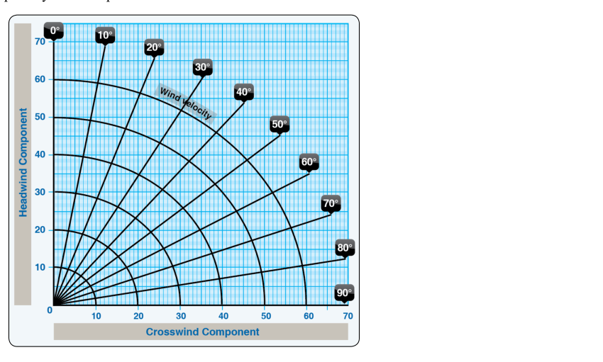
The wind component chart (also called the crosswind component graph) is published in the performance section of virtually every AFM/POH. It consists of curved arcs representing total wind speed and radiating straight lines representing the angular difference between wind direction and runway heading. The horizontal axis gives crosswind component; the vertical axis gives headwind or tailwind component.
To use the chart: determine the angle between the wind and the runway (always use the smaller angle, between 0° and 90°); find the arc corresponding to total wind speed; follow the arc to where it intersects the line for your angle; read directly left for crosswind and directly down for headwind. Using the earlier example, locate the 25-knot arc, slide along it to the 40° line, then read approximately 16 knots on the horizontal axis and 19 knots on the vertical axis — confirming the trigonometric calculation without requiring a calculator.
Proficiency with this chart under realistic conditions — low lighting, time pressure, or a cold cockpit — takes deliberate practice. The commercial ACS expects pilots to extract this data accurately and apply it to a performance scenario.
Field Approximations: The Clock Code
When a printed chart is unavailable or time is short, pilots use the clock code (sometimes called the percentage method or sine approximation). The method treats the wind angle in increments and assigns approximate percentages of total wind speed to the crosswind component:
- 10° off the runway: approximately 17% of total wind speed becomes crosswind
- 20° off the runway: approximately 34%
- 30° off the runway: approximately 50%
- 45° off the runway: approximately 71%
- 60° off the runway: approximately 87%
- 75° off the runway: approximately 97%
- 90° off the runway (pure crosswind): 100%
These figures are the actual sine values rounded to whole percentages. The most useful mental anchor: a wind 30° off the runway gives roughly half its speed as crosswind, and a wind 60° off the runway gives roughly 87%. These two data points alone allow a rapid sanity check during taxi or while copying ATIS.
Demonstrated Crosswind vs. Mandatory Limitation
This distinction is one of the most frequently tested topics at both the knowledge-test and oral-exam level, and it has genuine safety and legal implications.
Demonstrated Crosswind Component
The demonstrated crosswind component is the maximum crosswind value at which the test pilot actually flew the aircraft during FAA certification flight testing. The Airplane Flying Handbook (FAA-H-8083-3) is explicit on this point: the demonstrated crosswind value is informational, not necessarily a hard operational limit imposed by the aircraft's structural or aerodynamic design. In plain terms, the test pilot may have simply run out of suitable wind conditions on the day of testing. The aircraft may be capable of handling a higher crosswind — or it may not. The AFM/POH note accompanying the demonstrated value often reads to this effect, advising that operations above the demonstrated value require the pilot to exercise sound judgment.
Maximum Crosswind Limitation
Some aircraft AFMs go further and list a maximum crosswind limitation in the Limitations section — the section that 14 CFR Part 91 requires pilots to comply with as part of the operating limitations. When the Limitations section contains a specific maximum crosswind value, that number carries regulatory force. Exceeding it is not a judgment call; it is a violation. Pilots must read the AFM carefully and know which category their aircraft falls into.
Operational Considerations Under Parts 135 and 121
Commercial operators flying under 14 CFR Parts 135 or 121 face an additional layer of oversight. Company operations specifications (OpSpecs) approved by the FAA may impose crosswind limits that are more restrictive than the AFM value, accounting for fleet standardization, crew training levels, and route-specific runway conditions. A Part 135 pilot's personal crosswind comfort level is irrelevant when OpSpecs dictate a lower number — the OpSpec limit governs.
Runway Selection and Real-World Airmanship
When multiple runways are available, selecting the runway that minimizes the crosswind component is a fundamental crosswind management strategy. A pilot who requests or accepts the more favorable runway alignment proactively reduces risk rather than testing the limits of aircraft or personal capability. The AIM and FAA-H-8083-2 (Risk Management Handbook) both emphasize this kind of hazard mitigation as part of sound aeronautical decision-making.
Gusts add complexity. When the wind is reported as variable or gusty, pilots must account for the peak gust speed rather than the mean speed when calculating the crosswind component. A wind reported as 12G22 knots means the instantaneous crosswind component could be based on 22 knots, not 12. Using the mean speed for planning while the gust value briefly exceeds the aircraft's demonstrated limit is a classic go/no-go error.
Common Test Traps
- Using runway magnetic heading vs. true: Wind directions in aviation weather reports are given in degrees true (from upper-air reports and forecasts) or degrees magnetic (from ATIS/tower). ATIS and tower winds are reported in magnetic degrees. Runway headings on charts are magnetic. Match the reference frames before computing the angle.
- Confusing demonstrated with prohibited: Unless the AFM Limitations section explicitly prohibits operations above the demonstrated crosswind value, it is not a regulatory hard limit — though it is never wise to treat it as an invitation to push the boundary.
- Ignoring the tailwind component: A nearly perpendicular crosswind still has a small tailwind or headwind component. A tailwind component — however small — extends ground roll and must be factored into performance calculations separately.
- Applying wind angle to runway number instead of heading: Runway 27 has a heading of 270°, not 27°. Always convert the runway number to a three-digit heading before computing the angular difference.
- Treating the clock code as precise: The percentage approximations are useful for quick mental math but are not substitutes for the AFM wind component chart in a formal preflight or performance calculation.
Why This Matters for the Commercial Certificate
The commercial ACS requires applicants to demonstrate the ability to select an appropriate runway, accurately compute or estimate the crosswind component, compare it against aircraft data, and explain the regulatory distinction between demonstrated and limiting values. Examiners frequently present a scenario with a gusty, angled wind and ask the applicant to work through the math, choose between available runways, and articulate whether the conditions are within the aircraft's published envelope. A confident, accurate answer — grounded in the AFM, the AIM, and applicable CFR sections — demonstrates the level of systems knowledge and risk management judgment expected of a commercial pilot.