A propeller is far more than a spinning fan. It is a rotating system of miniature airfoils, and every fraction of an inch along each blade is doing aerodynamic work that is slightly different from the fractions beside it. Blade element theory is the analytical framework that dissects that work into manageable pieces, revealing exactly why propellers are twisted the way they are, why their efficiency rises and falls with airspeed, and why a constant-speed propeller is so valuable for commercial operations that demand performance across a wide flight envelope. For the commercial pilot written test and the ACS oral, this topic bridges advanced aerodynamics, propeller selection, and multi-regime performance planning.
How Blade Element Theory Works
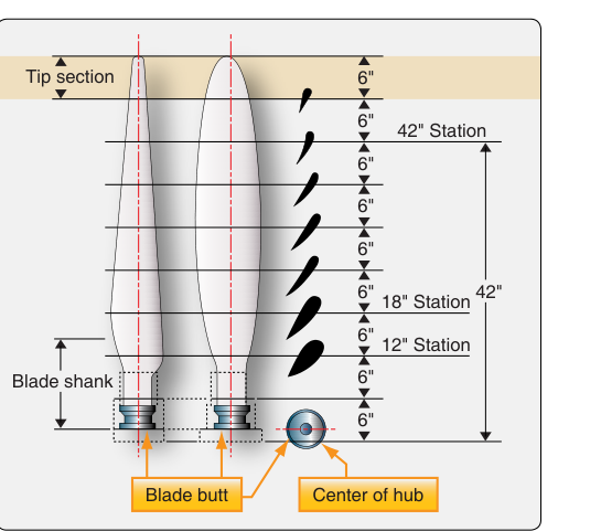
The central idea is straightforward: slice a propeller blade into dozens of thin segments—called blade elements—from root to tip and analyze each one independently as an airfoil. Each element has a defined chord, camber, and local velocity. When you combine all those elemental forces and integrate them across the blade span, you arrive at total thrust and total torque for the propeller as a whole.
The velocity triangle at each element
What makes the analysis interesting is that each blade element experiences two simultaneous velocities: the rotational velocity due to spinning (tangential, perpendicular to the blade span) and the forward velocity of the aircraft (axial, parallel to the propeller shaft). These two vectors add geometrically to produce a resultant relative wind that strikes each element at a specific angle. The blade's chord line makes a specific angle with the plane of rotation—the blade angle (sometimes called pitch angle). The difference between the blade angle and the direction of the resultant relative wind is the element's angle of attack. That angle determines how much lift (thrust-producing force) and drag (torque-producing force) the element generates, just as it does on a wing.
Why rotational speed varies from root to tip
Here is the fundamental geometric fact that drives everything else: every element on the blade completes one full revolution in the same fraction of a second, but elements near the tip trace a vastly larger circle than elements near the hub. Tip velocity is therefore much higher than root velocity. At typical general aviation RPM, the tip of a two-bladed propeller can be moving at several hundred feet per second while the root is moving at only a fraction of that speed. Because the axial (forward flight) velocity component is the same for every element, the ratio of forward-to-rotational velocity changes dramatically from root to tip. The resultant relative wind therefore arrives at a much steeper upward angle near the root than near the tip.
If the blade were geometrically flat—no twist—the root element would face a very high angle of attack (possibly into a stall) while the tip element would be at a shallow, inefficient angle. Thrust production would be terrible. The solution is geometric twist: the blade is manufactured with a progressively decreasing blade angle from root to tip. The root has a high (coarse) blade angle; the tip has a low (fine) blade angle. The twist is sized so that every element along the blade operates near its best lift-to-drag angle of attack simultaneously during the design flight condition, producing the maximum possible net thrust for a given shaft power input.
Propeller Efficiency and the Advance Ratio
Propeller efficiency is defined as the ratio of useful thrust power output (thrust multiplied by true airspeed) to the shaft horsepower delivered by the engine. It is expressed as a percentage, and it is almost never 100 percent because power is inevitably lost to blade profile drag, induced drag at the blade tips (tip vortices), and the rotational kinetic energy imparted to the slipstream that does not contribute to forward thrust.
The advance ratio
Efficiency is most meaningfully plotted against the advance ratio, symbolized as J and defined as forward velocity divided by the product of propeller rotational speed (in revolutions per second) and propeller diameter. In plain language, the advance ratio expresses how far the propeller advances forward for each revolution. At low airspeed and high RPM—ground run or initial takeoff roll—the advance ratio is small: the propeller is spinning fast relative to how far the aircraft is moving. At cruise, the ratio is higher.
Reading the efficiency curve
When propeller efficiency is plotted against advance ratio, the resulting curve has a characteristic shape that every commercial candidate should be able to describe from memory:
- Left side (low advance ratio): Efficiency is low. The blade elements are operating at high angles of attack, producing thrust but also generating significant drag and churning the air in a way that imparts rotational energy to the slipstream rather than axial momentum. This is why static thrust at the start of a takeoff roll, while large in absolute terms, represents poor efficiency in the thermodynamic sense.
- Peak efficiency: As airspeed builds and advance ratio rises, each blade element moves toward its optimum angle of attack. Efficiency climbs to a distinct maximum—often cited as high as 85–88 percent for a well-designed propeller at its design condition.
- Right side (high advance ratio): Beyond the peak, the blade angle of attack becomes too shallow. Elements generate little lift relative to drag, thrust falls rapidly, and efficiency drops steeply. At the extreme, the blades can reach a zero-thrust or even negative-thrust condition.
Fixed-pitch versus constant-speed propellers
A fixed-pitch propeller has a single blade angle that cannot change in flight. Its efficiency curve is narrow and sharply peaked: the propeller is efficient in only a small band of advance ratios, meaning one combination of airspeed and RPM. The designer must choose between optimizing for climb (lower pitch, higher RPM, good low-speed thrust) or cruise (higher pitch, more efficient at speed). Either way, the propeller underperforms significantly outside its design regime.
A constant-speed (variable-pitch) propeller uses a governor to continuously adjust blade angle, maintaining the pilot-selected RPM as power setting and airspeed change. By changing blade angle, the governor keeps blade element angles of attack near their optimum across a wide range of advance ratios. The result is an efficiency curve that is broader and flatter—peak efficiency is similar to a good fixed-pitch design, but that high efficiency is sustained from climb speeds all the way through cruise. This is a decisive performance advantage for commercial aircraft that must operate efficiently at multiple altitudes, weights, and airspeeds.
Blade Element Theory and Propeller Aerodynamic Effects
The same blade element analysis that explains thrust also explains the propeller's secondary aerodynamic effects, all of which are tested at the commercial level.
Torque reaction
Every blade element produces a small drag force opposing the direction of rotation. Integrated across the blade, that drag becomes the total propeller torque that the engine must overcome. By Newton's third law, an equal and opposite reaction torque acts on the airframe, rolling the aircraft opposite to propeller rotation. In most U.S. single-engine aircraft with a clockwise-rotating propeller (as seen from the cockpit), this creates a left-rolling tendency that must be corrected with aileron input, and it is most pronounced at low airspeed and high power settings such as during takeoff and climb.
Asymmetric blade effect (P-factor)
When the aircraft is in a nose-high attitude, the propeller disk is tilted relative to the oncoming airflow. The descending blade (on the right side of the disk for a clockwise-rotating propeller) moves through the air at a greater effective angle of attack than the ascending blade on the left. Blade element theory shows directly why: because the propeller disk is tilted relative to the flight path, the descending blade travels a greater distance—and therefore sweeps through a higher resultant velocity and angle of attack—than the ascending blade, which travels a comparatively shorter arc relative to the oncoming airflow. The descending blade generates more thrust than the ascending blade, creating a left-yawing tendency that is most pronounced during low-speed, high-power, nose-high flight—exactly the condition during a takeoff climb.
Key Numbers and Rules
- Propeller efficiency is the ratio of thrust power out to shaft power in; real-world peaks are often cited as high as roughly 85 to 88 percent for well-designed propellers.
- Blade twist exists to equalize angles of attack from root to tip; without it, root elements would stall while tip elements flew at inefficient shallow angles.
- The efficiency curve peaks at the design advance ratio and falls on both sides; there is no regime where efficiency increases indefinitely with speed.
- A constant-speed propeller's efficiency curve is broader than that of a fixed-pitch propeller, sustaining high efficiency across multiple flight regimes.
- P-factor is greatest at high angle of attack and high power—takeoff climb—and is minimal in level cruise where the propeller disk is nearly perpendicular to the flight path.
Common Test Traps
- Efficiency does not keep rising with speed. Some distractors suggest efficiency increases continuously as airspeed increases. It peaks at the design advance ratio, then falls sharply.
- Confusing blade angle with angle of attack. Blade angle is the geometric angle of the chord to the plane of rotation—set by the manufacturer or governor. Angle of attack is the angle between the chord and the actual resultant relative wind. They are related but not the same, especially as airspeed changes.
- Confusing propeller twist with wing washout. Both involve decreasing angle from root to tip, but their purposes differ. Propeller twist compensates for the velocity gradient along the blade. Wing washout is primarily a stall-management device ensuring the root stalls before the tip.
- Fixed-pitch propellers can be efficient—but only at one condition. A test question may state that a fixed-pitch propeller is less efficient than a constant-speed propeller. More precisely, it achieves similar peak efficiency but only at its specific design point; across a broader range of conditions the constant-speed design wins decisively.
- P-factor direction depends on rotation direction. The standard left-yaw tendency applies to propellers rotating clockwise as seen from the cockpit. A few aircraft (notably some twins) have counter-rotating or opposite-rotation propellers, changing which side the descending blade is on.
Memory aid
Think of the propeller blade as a wing standing on its side: blade lift becomes thrust, blade drag becomes torque. The blade must twist for the same reason that a high-aspect-ratio wing sometimes has geometric twist built in—to keep every section flying at an efficient angle of attack at the same time. The phrase "twist equals efficiency, advance ratio equals the sweet spot" encapsulates the two core ideas of blade element theory.