Every fixed-wing aircraft certified under FAA regulations must provide the pilot with adequate warning before a full aerodynamic stall occurs. This is not merely good engineering practice—it is a regulatory requirement. The stall warning system bridges the gap between normal flight and the dangerous loss of lift that follows exceeding the wing's critical angle of attack (AOA). For airframe technicians, understanding how these systems work, how to inspect and maintain them, and what failure modes look like is essential knowledge for both the FAA AMT knowledge exam and real-world hangar work.
Stall warning systems come in several forms, but two dominate the airframe world: the simple aerodynamic vane (lift detector) sensor used on most light general aviation aircraft, and the sophisticated stick shaker system found on transport-category airplanes. Both serve the same fundamental purpose—alerting the flight crew before the wing stalls—but they operate through entirely different mechanisms and require very different maintenance approaches.
Aerodynamic Principles Behind Stall Warning
To appreciate why these systems are designed the way they are, you first need to understand what they are detecting. A wing stalls not because of low airspeed per se, but because it has exceeded its critical angle of attack—the angle between the chord line and the relative wind beyond which airflow separates from the upper surface and lift collapses. For most general aviation airfoils, this critical AOA is somewhere in the range of 16 to 20 degrees, though the exact value depends on the airfoil design.
The key insight for stall warning design is that changes in the local airflow near the wing's leading edge provide an early indication that the critical AOA is being approached. As AOA increases, the stagnation point—where the oncoming airflow splits to travel over and under the wing—migrates downward along the leading edge toward the lower surface. Designers exploit this predictable movement to trigger a warning before the full stall is reached.
Vane-Type Stall Warning Sensors
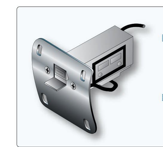
The vane-type stall warning system, sometimes called a lift detector or AOA vane sensor, is the most common device on single-engine and light twin aircraft. It is elegantly simple: a small aerodynamically shaped tab or vane protrudes from the wing's leading edge, typically near the root on the left wing. The vane is mounted on a pivot and is free to rotate.
During normal flight at moderate angles of attack, the local airflow at the leading edge holds the vane in a downward or neutral position. As the pilot increases the AOA approaching the critical value, the stagnation point moves below the vane. The airflow now strikes the underside of the vane and pushes it upward. When the vane rotates far enough, it closes an electrical switch. That switch completes a circuit to an aural warning horn in the cockpit, which sounds continuously until the pilot reduces AOA.
The vane is carefully calibrated during manufacturing and certification so that the horn activates at approximately 5 to 10 knots above the actual stall speed in a given configuration. This margin gives the pilot meaningful warning time without crying wolf during normal maneuvering. The switch mechanism is simple—typically a reed switch or a micro-switch—and the circuit often includes the aircraft's master electrical bus, which means the system is inoperative if the master switch is off. Some installations include a test button in the cockpit that directly activates the horn to verify the warning circuit, though the test does not verify the vane's aerodynamic response.
Vane Sensor Maintenance Considerations
Airframe technicians must inspect vane sensors carefully during routine maintenance. Key inspection points include: verifying the vane moves freely on its pivot without binding or stiffness caused by corrosion, paint buildup, or insect intrusion; checking the electrical connector and wiring for chafing and secure attachment; and confirming that the vane is not bent, deformed, or missing entirely. Because the vane protrudes from the leading edge, it is vulnerable to ramp damage, ice accumulation, and bird strikes. Replacement vanes must be the correct part number and installed in the exact position specified in the aircraft maintenance manual—even a slight angular error can shift the activation AOA and compromise the warning margin. Any time the leading edge skin is repaired or replaced in the vicinity of the vane, the sensor's calibration and freedom of movement must be re-verified before return to service.
Stick Shaker Systems
Transport-category aircraft—airliners, large business jets, and many turboprops—employ a far more forceful and attention-commanding device: the stick shaker. The name is literal. A small but powerful electric motor with an eccentric weight is mounted directly on the control column (or yoke assembly). When the system detects an approaching stall condition, the motor spins rapidly, and the eccentric weight creates vibration that shakes the entire control column in the pilot's hands. The physical sensation is unmistakable, even in a high-workload environment.
Stick shakers are almost always paired with a stall warning computer or AOA processor rather than a simple switch. The computer takes inputs from one or more dedicated AOA transducers—vane-type sensors that output an analog voltage or digital signal proportional to the local AOA rather than simply closing a switch. The computer also typically receives air data inputs including airspeed, altitude, Mach number, and flap/slat position so it can compute a precise activation threshold appropriate for the current flight configuration. High-altitude flight, for instance, changes the relationship between indicated airspeed and stall margin, and flap extension significantly lowers the stall AOA; the computer accounts for all of these variables.
On most large transport aircraft, two independent stick shaker channels are installed—one for the captain's column and one for the first officer's column—each fed by its own AOA sensor. This redundancy ensures that a failure of one channel does not leave the crew without warning, and it also means that a faulty sensor cannot trigger both shakers simultaneously (which would be a nuisance during normal flight). The two systems are cross-monitored, and disagreement between them can trigger a crew alert.
Stick Pusher Systems
Some high-performance aircraft go one step further and add a stick pusher (also called a stall prevention system) to the stick shaker installation. If the crew does not respond to the shaker and AOA continues to increase toward the actual stall, the stick pusher actuator applies a forceful forward push to the control column—physically driving the nose down and reducing AOA. Stick pushers are common on aircraft with T-tail configurations, where a deep stall is possible and recovery may be impossible with normal pilot inputs alone. Maintenance of stick pushers involves careful force calibration and functional testing per the maintenance manual to ensure the system activates at the correct AOA and applies the correct force without being so aggressive as to overpower a pilot intentionally commanding the maneuver.
Why Stall Warning Systems Matter
Stall/spin accidents have historically been among the leading causes of fatal general aviation crashes, frequently occurring during the traffic pattern at low altitude where recovery is impossible. A functioning stall warning system provides the critical extra seconds a pilot needs to recognize the situation and recover. For AMTs, ensuring these systems are airworthy is directly tied to pilot survivability. An inoperative stall warning vane that goes unnoticed during an annual inspection, or a stick shaker motor that fails silently between maintenance intervals, removes a layer of protection that may be decisive in an emergency.
Key Numbers and Rules
- Warning margin: Stall warning systems are typically required to activate at least 5 knots or 5% of stall speed (whichever is greater) above the unaccelerated stall speed in any configuration—this margin is established during FAA type certification testing.
- Vane freedom of movement: The vane must pivot freely through its full travel; any binding requires correction before return to service.
- Stick shaker motor inspection: Check for secure mounting, correct wiring polarity, brush wear (on brushed DC motors), and verify functional test per the AMM activates at the correct AOA input.
- AOA transducer heating: On transport aircraft, AOA vanes often have integral heaters to prevent icing; confirm heater continuity and proper operation during preflight inspections and maintenance checks.
- Inoperative stall warning: Under 14 CFR Part 91, an inoperative stall warning system is generally not permitted for flight unless specifically authorized by the MEL (Minimum Equipment List) for that aircraft type.
- Calibration after leading-edge work: Any repair, replacement, or alteration near a stall warning vane requires re-verification of the system per the maintenance manual before releasing the aircraft.
Common Test Traps
- Stall speed vs. AOA: The FAA exam may try to get you to say stall warning detects low airspeed. Wrong—it detects a critical angle of attack. An aircraft can stall at any airspeed if AOA is high enough.
- Vane test button limits: The cockpit test button checks the horn and electrical circuit only—it does NOT verify that the vane itself responds correctly to airflow. Candidates often confuse a successful horn test with a complete system check.
- Stick shaker vs. stick pusher: These are separate devices with separate functions. The shaker warns; the pusher acts. Not all aircraft with shakers have pushers.
- Single vs. dual channels: Light aircraft have one vane and one horn. Transport aircraft typically have dual, independent AOA channels feeding separate shaker motors on each control column—know the difference.
- Inoperative system airworthiness: Students sometimes assume a non-functional stall warning is a minor discrepancy. In most cases it makes the aircraft unairworthy for flight without MEL authorization—a commonly tested regulatory point.