Every piston and turbine-powered aircraft depends on a carefully engineered fuel delivery system to move fuel from the tanks to the engine with the right pressure, flow rate, and reliability. At the heart of most of these systems are two types of pumps working in concert: the engine-driven fuel pump and the boost pump (also called the auxiliary or electrical fuel pump). Together they form a redundant delivery architecture that keeps fuel flowing even when one component fails or conditions change. For the Aviation Maintenance Technician (AMT) preparing for the FAA Airframe written and oral examinations, a thorough understanding of both pump types — how they work mechanically, how they interact, when each is used, and what happens when either fails — is indispensable.
This article covers piston-engine fuel systems primarily, with notes on turbine applications where the principles diverge. The governing technical standards are found in the Aviation Maintenance Handbook – Airframe (FAA-H-8083-31) and in 14 CFR Part 23 airworthiness standards for normal-category airplanes.
The Engine-Driven Fuel Pump
The engine-driven fuel pump is the primary fuel pump on most reciprocating-engine aircraft. It is mechanically coupled to the engine's accessory drive gear train, meaning it spins whenever the engine is running. Because it depends entirely on engine rotation, it produces no fuel flow when the engine is stopped — a critical limitation that directly explains why boost pumps exist.
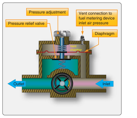
Most engine-driven pumps used in light aircraft are vane-type (rotary vane) pumps. Inside the pump housing, a slotted rotor holds a series of spring-loaded vanes. As the rotor turns eccentrically within the housing, the spaces between adjacent vanes alternately expand (drawing fuel in) and contract (pushing fuel out). This produces a relatively smooth, continuous flow of fuel at a pressure and volume determined by rotor speed — which is a fixed ratio of engine RPM. Because output pressure rises with RPM, a relief valve is built into the pump circuit to limit maximum pressure and protect downstream components (carburetor float valves, fuel-injector manifold valves, etc.). Excess fuel beyond the relief valve setting is bypassed back to the pump inlet or returned to the tank.
A key design feature is the bypass (check) valve integrated into or immediately downstream of the engine-driven pump. This valve allows fuel to flow around the pump if the pump fails or is removed. Without it, a seized engine-driven pump would block fuel flow entirely, even if a boost pump were operating. The bypass valve ensures the boost pump can supply fuel through the same lines the engine-driven pump normally uses.
Boost Pumps — Design and Types
The boost pump is an electrically powered pump, independent of engine rotation. Because it runs on aircraft electrical power rather than engine mechanical power, it can deliver fuel before engine start, during engine-out glides, and whenever the engine-driven pump is insufficient or has failed. Most boost pumps are submerged centrifugal (impeller-type) pumps located inside the fuel tank or fuel cell, at the lowest accessible point to ensure they remain covered with fuel and avoid vapor lock. Submerging the pump in cold fuel also extends the motor's service life and reduces the risk of fuel vaporization in the pump inlet lines.
Centrifugal boost pumps are non-positive-displacement devices: they add pressure to the fuel stream by spinning an impeller at high speed, but they do not seal discrete volumes of fluid against leakage. This means a centrifugal boost pump by itself may not develop enough pressure to satisfy certain fuel-injected engines at all conditions, which is why the higher-pressure engine-driven vane pump remains the primary supply pump during normal flight. However, a centrifugal boost pump produces sufficient inlet pressure (positive head) to prevent vapor lock and cavitation at the engine-driven pump inlet — one of its most valuable functions at high altitude and during hot-day operations.
Some high-performance or turbine-powered aircraft use positive-displacement boost pumps (gear-type or vane-type electrically driven), which can deliver full system pressure independently. These are common wherever the boost pump must serve as a true standby primary pump.
How the Two Pumps Work Together
Under normal operating conditions on a light piston aircraft, the engine-driven pump is the active primary pump, and the boost pump operates either continuously (in some designs) or on demand. The relationship between their pressures is deliberate: boost pump output pressure is typically calibrated to be slightly lower than or comparable to the engine-driven pump's pressure — close enough to provide effective backup and priming pressure, but not so high that it overrides normal engine-driven pump operation or exceeds the relief valve setting. This means the engine-driven pump dominates the fuel supply under normal flight conditions, and the boost pump, if running simultaneously, simply provides positive inlet pressure to the engine-driven pump without overpowering it. The fuel system is designed so both can run together safely.
When the engine-driven pump fails, its built-in bypass valve opens, and the boost pump takes over as the sole fuel delivery device. The pilot selects the boost pump on (or it may be automatic in some installations), and fuel flows through the bypass path around the failed engine-driven pump. The aircraft may then have reduced fuel pressure compared to normal, so pilots are trained to monitor the fuel pressure gauge and land as soon as practicable.
Operational Use of Boost Pumps
Standard operating procedures typically call for boost pump use during the following phases:
- Engine start: The engine-driven pump cannot supply fuel before the engine fires. The boost pump primes the lines and ensures fuel reaches the carburetor or fuel-injection system from the first rotation of the starter.
- Takeoff and landing: These are the most critical and demanding phases of flight. Having the boost pump on means that if the engine-driven pump fails at a critical moment, fuel delivery is uninterrupted without any pilot action.
- High-altitude cruise: At altitude, fuel in low-pressure areas of the fuel system can vaporize (vapor lock). The boost pump maintains positive pressure throughout the inlet lines, suppressing vapor formation.
- Fuel tank switching: When changing fuel tanks in flight, there may be a momentary interruption as fuel from the new tank reaches the pump. The boost pump provides a continuous supply buffer during this transition.
- Engine-driven pump failure: The boost pump is switched on immediately and remains on for the remainder of the flight.
During normal cruise in many light aircraft, pilots turn the boost pump off to reduce electrical load and pump wear, relying on the engine-driven pump alone. Pilots are trained to monitor fuel pressure; a drop signals pump trouble and calls for immediate boost pump activation.
Maintenance Considerations for AMTs
From a maintenance perspective, both pump types require regular inspection and adherence to the manufacturer's maintenance manual and the Instructions for Continued Airworthiness (ICA). Key AMT tasks and inspection points include:
- Engine-driven pump: Inspecting the pump body for cracks and leaks, checking the relief valve setting against specifications, verifying the condition of drive couplings (many use a shear section in the drive shaft that is designed to break before accessory gearbox damage occurs if the pump seizes), and confirming the bypass valve functions correctly.
- Boost pump: Checking electrical connections for corrosion and security, verifying pump motor amperage draw against specifications (excessive draw may indicate bearing wear), inspecting the pump inlet screen or filter for debris, and confirming the pump produces adequate pressure on a fuel pressure gauge check.
- Fuel filters and screens: Both pump types depend on clean fuel. The AMT must inspect and clean or replace in-line strainers and gascolators according to inspection intervals.
- Fuel pressure checks: After pump replacement or any system disturbance, a ground run to verify fuel pressure within the manufacturer's specified range (typically measured in PSI at the carburetor inlet or fuel injector manifold) is required before return to service.
- Airworthiness Directives (ADs): Certain engine-driven pump models have been subject to ADs addressing internal seal failures or drive coupling defects. The AMT must always check the current AD status for installed pump part numbers.
Turbine Engine Applications
Turbine engines demand significantly higher fuel flow rates and pressures than piston engines. In turbine systems, boost pumps (often called low-pressure pumps or tank pumps) are typically submerged centrifugal pumps in each tank. Their job is to deliver fuel at sufficient pressure to the engine's high-pressure engine-driven fuel pump, which then raises pressure dramatically (hundreds of PSI) for atomization through fuel nozzles. If the boost pump fails in a turbine system, the engine-driven high-pressure pump may induce vapor lock or cavitation, potentially causing a flameout — making boost pump health critically important in turbine operations.
Key Numbers and Rules
- Engine-driven pump relief valve settings and boost pump output pressures are aircraft and engine specific — always consult the applicable Approved Flight Manual (AFM) and maintenance manual for exact values.
- Most light aircraft engine-driven fuel pump output pressures range from approximately 0.5 to 8 PSI for carburetor engines, and higher for fuel-injected systems.
- Boost pump electrical current draw specs are provided by the manufacturer; a draw significantly above specification indicates a worn motor or mechanical restriction.
- 14 CFR 23.955 (pre-2017 amendment basis aircraft) requires that the fuel system provide fuel at a rate and pressure adequate to properly supply the engine under each likely operating condition, including maneuvers appropriate to the airplane's category; specific test flow rates (such as 150% of takeoff fuel consumption for certain gravity-feed systems) are specified within 23.955 itself rather than a single flat percentage applying to all systems.
- Shear-section drive couplings are not field-repairable — a sheared coupling means pump replacement and an investigation into why the pump seized.
Common Test Traps
- Confusing pump types: The engine-driven pump is the primary pump; the boost pump is auxiliary. Test questions sometimes describe a failure scenario and ask which pump takes over — it is always the boost pump covering for a failed engine-driven pump, not the reverse.
- Bypass valve function: Many students forget that the engine-driven pump's bypass valve is what allows the boost pump to supply fuel when the engine-driven pump has failed. Without this valve, a failed engine-driven pump would block flow entirely.
- Centrifugal vs. positive-displacement: Centrifugal boost pumps are not self-priming in the same sense as a vane pump and cannot seal discrete fuel volumes — they rely on being submerged. Test questions may ask why boost pumps are placed inside or at the bottom of fuel tanks.
- When to turn the boost pump on: A classic exam scenario asks at what phase of flight the boost pump should be ON. The answer: takeoff, landing, engine start, high-altitude operations, tank switching, and any time the engine-driven pump is suspect or failed.
- Relief valve purpose: The relief valve on an engine-driven pump limits maximum output pressure and bypasses excess fuel back to the inlet — it does not regulate flow to the engine directly. Confusing it with a flow divider or fuel control unit is a common error.