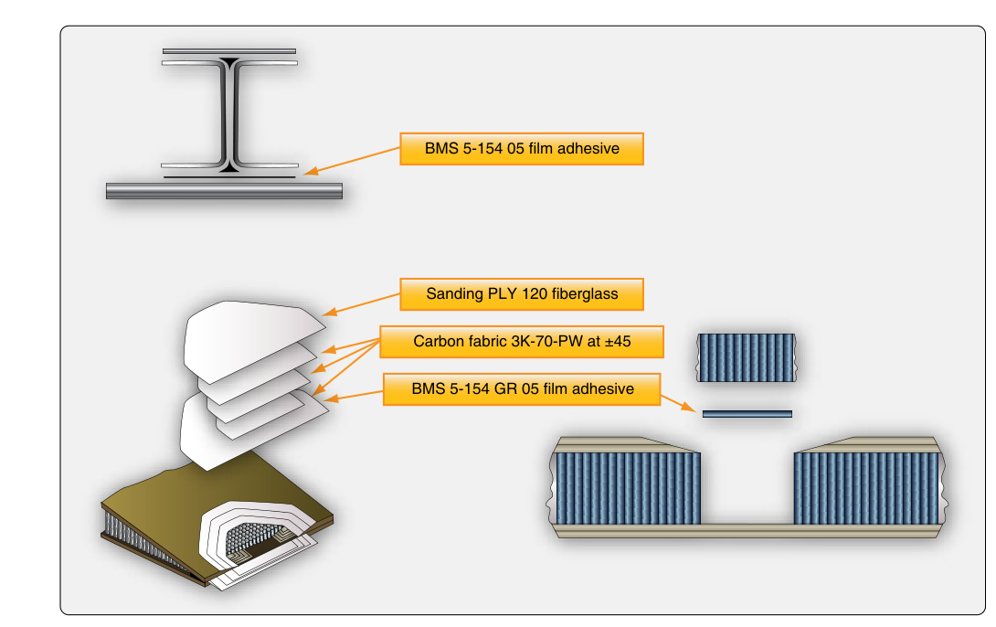
Modern aircraft rely heavily on composite materials — structures built from reinforcing fibers bonded together with a resin matrix — because they offer exceptional strength-to-weight ratios, resistance to corrosion, and the ability to be molded into complex aerodynamic shapes. As an Aviation Maintenance Technician (AMT), understanding how fiberglass and carbon fiber components are fabricated and repaired is not only an FAA knowledge-test requirement but a genuine hands-on safety skill. A poorly executed composite repair can introduce hidden delaminations, disbonds, or stress concentrations that are invisible to the naked eye yet catastrophic under flight loads.
This article walks through the fundamentals of composite layup and repair — the materials involved, the step-by-step fabrication and repair processes, cure methods, quality inspection, and the regulatory framework that governs composite work on certificated aircraft.
Composite Materials: The Building Blocks
Every composite structure consists of two primary components: the reinforcement (the fibers) and the matrix (the resin). The fibers carry the structural loads, while the resin transfers loads between fibers, protects them from the environment, and gives the part its shape.
Fiberglass
Fiberglass uses glass fibers woven or arranged into a fabric or mat. It is relatively inexpensive, easy to work with, electrically non-conductive, and transparent to radio frequencies — making it ideal for radomes, fairings, and control surface skins. The most common types used in aviation are E-glass (general-purpose, economical) and S-glass (higher strength and stiffness, used in more demanding applications). Fiberglass is typically paired with epoxy, polyester, or vinylester resins.
Carbon Fiber (Graphite)
Carbon fiber reinforced polymer (CFRP) uses carbon filaments, each only a few micrometers in diameter, which are woven or laid in sheets called plies. Carbon fiber is significantly stiffer and stronger than fiberglass at a lower weight, making it the material of choice for primary structure on modern transport-category and high-performance aircraft. However, it requires careful handling: carbon fiber is electrically conductive (it can cause galvanic corrosion when in direct contact with aluminum), it is brittle in compression compared to metal, and damage can be extremely difficult to detect visually. Carbon fiber is almost exclusively paired with epoxy resin systems.
Resin Systems
The resin bonds the fibers and gives the laminate its shape. Epoxy resins dominate aviation composites because of their excellent adhesion, low shrinkage during cure, and resistance to moisture and chemicals. Resins come in two forms relevant to layup: wet systems where liquid resin is mixed with a hardener at the time of use, and prepreg systems where the fiber is pre-impregnated with resin and stored frozen (commonly around 0°F/-18°C, per the manufacturer's specification) until needed.
Layup Techniques
Wet Layup (Hand Layup)
Wet layup is the most common field-repair method. The technician mixes resin and hardener in the manufacturer-specified ratio — getting this ratio wrong is one of the most common errors and leads to incomplete cure, soft spots, and poor mechanical properties. Fabric is cut to the correct shape and fiber orientation, then placed onto the mold or damaged area. Resin is applied by brush or roller and worked into the fabric to wet out the fibers fully without trapping air bubbles. Each successive ply is added in the specified orientation (ply orientation dramatically affects strength direction — a 0°/90° layup resists loads differently than a quasi-isotropic ±45° schedule). After all plies are placed, a peel ply and breather cloth are often applied before vacuum bagging.
Prepreg Layup
Prepreg (pre-impregnated) materials have resin already incorporated into the fiber at a controlled fiber-to-resin ratio. They are stored frozen to prevent premature cure. Prepreg layup produces more consistent, higher-quality laminates with better fiber-to-resin ratios than wet layup, but requires an oven or autoclave for cure. Technicians must track the out-time (time the material has been out of the freezer) carefully — material that has exceeded its out-time specification must be discarded. Prepreg is more commonly used in manufacturing than field repair, but some approved repair data specify prepreg patches.
Vacuum Bagging
Regardless of the layup method, aviation-quality composite repairs almost always use vacuum bagging to consolidate the laminate. A flexible bag is sealed over the layup, and a vacuum pump draws air out, applying atmospheric pressure across the entire repair area (a full vacuum can only approach standard atmospheric pressure, about 14.7 psi at sea level; actual pressure achieved depends on the vacuum level pulled and system leak-tightness). This consolidates the plies, removes trapped air and excess resin, and ensures intimate contact between layers. The vacuum is held throughout the cure cycle. Breather cloth distributes vacuum uniformly, and a release film or peel ply prevents the bag from bonding to the part.
Repair Techniques
Damage Assessment First
Before any repair begins, the extent of damage must be fully characterized. Visual inspection alone is insufficient for composites. Accepted NDI (Non-Destructive Inspection) methods include coin tap testing (a change in resonance indicates delamination or disbond), ultrasonic inspection, and thermographic inspection. The damage area must be mapped out so the repair patch covers all affected material with adequate overlap.
Scarf and Stepped Repairs
The two primary structural repair geometries are the scarf repair and the stepped-lap repair. In a scarf repair, the damaged laminate is ground away at a shallow taper angle — typically specified as a ratio such as 1:20 to 1:50 (rise over run), meaning for every ply of thickness, the taper extends 20 to 50 times that thickness laterally. This gradual taper transfers load smoothly through the patch. In a stepped-lap repair, material is removed in discrete concentric steps, one ply per step, creating a staircase profile. Each replacement ply overlaps one step. Both methods restore the load path through the original laminate. Scarf repairs are generally preferred for thin laminates; stepped repairs are common on thicker structures. The specific repair geometry, ply count, orientation, and dimensions must always come from the approved repair data — either the Structural Repair Manual (SRM), manufacturer's repair documentation, or an approved data source such as a Designated Engineering Representative (DER) repair.
Bonded Patch Repairs (External)
For non-structural or lightly loaded components, an external bonded patch may be permissible. Fabric plies, each slightly larger than the last (stepped outward), are applied over the cleaned and abraded repair area. The first ply covers only the damage area, and each subsequent ply extends beyond the previous by a specified overlap distance — commonly 25 mm (approximately 1 inch) per ply. This creates a smooth load transfer into the parent structure. Surface preparation is critical: the area must be sanded, cleaned with approved solvents, and kept free of moisture and contamination before resin application.
Cure Methods
Composite repairs must be cured at the temperature and time specified by the resin manufacturer or the repair data. Common options include room-temperature cure (some epoxies cure at ambient temperature, but typically produce lower final properties), heat blanket cure (an electric resistance blanket placed over the bagged repair, controlled by a temperature controller), and oven or autoclave cure (required for prepreg and high-performance structural repairs). The cure cycle typically specifies a ramp rate (°F or °C per minute), a hold temperature, a hold time, and a cool-down rate. Deviation from the cure cycle can result in residual stresses, incomplete cure, or thermal damage to surrounding structure.
Key Numbers and Rules
- Mixing ratio: Always follow the manufacturer's specified resin-to-hardener ratio by weight or volume — even small errors cause significant property degradation.
- Scarf ratio: Commonly 1:20 to 1:50 depending on the structure and loading; always use the SRM or approved data value.
- Ply overlap (bonded patch): Typically a minimum of 25 mm (≈1 inch) per ply beyond the previous ply.
- Vacuum level: Required vacuum levels vary by repair specification and material — the FAA handbook does not mandate a single numeric threshold; always follow the applicable repair data, and ensure the system is held stable with no leaks.
- Out-time for prepreg: Tracked from first removal from freezer; total cumulative out-time must not exceed the material specification limit (varies by product, typically measured in hours at room temperature).
- Carbon fiber galvanic isolation: Carbon fiber must be isolated from aluminum structure using fiberglass plies or other approved barriers to prevent galvanic corrosion.
- Approved data requirement: Per 14 CFR 43.13(a), maintenance and repairs must be performed using methods, techniques, and practices acceptable to the Administrator; major repairs generally must be performed in accordance with approved data, while minor repairs may be performed using acceptable (not necessarily FAA-approved) data.
Common Test Traps
- Mixing ratio errors: Test questions may imply that a slightly off ratio is acceptable. It is not — the ratio must be exact per manufacturer's specifications. An incorrect ratio produces an incompletely cured or brittle laminate.
- Confusing scarf angle direction: A larger scarf ratio number (e.g., 1:50 vs. 1:20) means a shallower, more gradual taper — not a steeper one. Shallower tapers provide better load transfer.
- Assuming visual inspection is sufficient: Composite damage — especially delamination — is frequently invisible on the surface. Coin tap or ultrasonic inspection is required to fully map damage extent.
- Carbon fiber conductivity: Carbon fiber is electrically conductive; fiberglass is not. Confusing the two leads to incorrect answers about galvanic corrosion risk and lightning strike protection requirements.
- Cure temperature shortcuts: Elevating cure temperature above the specification to speed up a repair can cause thermal damage, residual stress, or degradation of adjacent materials such as foam core or adhesive films. Always follow the approved cure cycle.