Fire protection systems are among the most safety-critical installations on any certificated aircraft. A fire in flight or on the ground can escalate from an anomaly to a catastrophe within seconds, so aviation maintenance technicians (AMTs) must understand not only how these systems work but also how to inspect them correctly, maintain them to airworthy condition, and comply with all applicable FAA regulations and manufacturer requirements. Whether you are maintaining a single-engine piston trainer or a transport-category turbine aircraft, the principles of fire protection inspection and maintenance are foundational to every airframe rating.
This article covers the major components of aircraft fire protection systems, the inspection techniques used to evaluate them, the maintenance actions required to keep them serviceable, and the regulatory framework—drawn from 14 CFR, FAA handbooks, and applicable advisory circulars—that governs this work.
Overview of Aircraft Fire Protection Systems
Aircraft fire protection systems consist of two broad functional categories: fire detection systems, which sense the presence of heat, flame, or combustion byproducts, and fire extinguishing systems, which deliver suppressing agents to the affected zone. Both categories must function together reliably; a detection system that fails to alarm is as dangerous as an extinguisher that fails to discharge.
Detection systems rely on one or more of the following sensor technologies:
- Thermocouple detectors — Operate on the rate-of-temperature-rise principle. They generate an electrical signal only when temperature increases rapidly, making them useful for detecting fast-developing fires but less sensitive to slow, smoldering conditions.
- Thermal switch (spot) detectors — Bimetallic switches that close at a specific temperature threshold. They are simple, reliable, and commonly found in wheel wells and baggage compartments.
- Continuous-loop detectors — Such as the Fenwal and Kidde systems, routed throughout an engine nacelle or other fire zone; Kidde-type systems use a single wire with a ceramic thermistor core whose resistance decreases as temperature rises, while Fenwal-type systems use two wires separated by a eutectic salt core that melts and shorts the wires together at a set temperature. They respond to either average temperature elevation or a localized hot spot along the loop, providing more comprehensive coverage than spot detectors.
- Optical (infrared or ultraviolet) detectors — Sense the radiation signature of actual flames. They are fast-responding but susceptible to false alarms from sunlight or other radiation sources, so they are often used in combination with other sensor types.
- Smoke detectors — Found in lavatories, cargo compartments, and avionics bays. They use either photoelectric (light-scattering) or ionization principles to detect combustion particles in the air.
- Carbon monoxide (CO) detectors — Primarily used in cabin or cockpit areas to warn of CO intrusion from exhaust systems.
Fire extinguishing systems store a pressurized agent in one or more cylinders (containers) and route it via tubing and distribution rings or nozzles into the protected zone. The most common agents in certificated aircraft are Halon 1301 (bromotrifluoromethane) in legacy systems, and environmentally compliant alternatives such as HFC-227ea (Halon replacement agents) in newer designs. Dry chemical and CO₂ systems appear in some portable and ground-support contexts but are not typical in turbine nacelle systems.
How Fire Protection Systems Work
When a continuous-loop detector senses a temperature that exceeds its design threshold along any portion of its length, its resistance drops (in Kidde thermistor designs) or the eutectic salt core melts and shorts the two wires together (in Fenwal designs), completing a circuit that triggers the fire warning light and aural alert on the flight deck. The crew then verifies the warning, pulls the fire handle, and—if warranted—activates the extinguishing agent by rotating or pressing the handle.
Pulling the fire handle typically accomplishes several actions simultaneously: it closes fuel shutoff valves, closes hydraulic shutoff valves, disconnects the generator, closes bleed-air valves, and arms the extinguisher squib circuits. Each of these actions isolates the engine or APU from aircraft systems to prevent feeding the fire. The extinguisher then delivers agent through a distribution manifold designed to flood the fire zone. Many transport aircraft carry two extinguisher shots (referred to as the "first shot" and "second shot" or "reserve") to handle persistent fires.
Inspection Requirements and Techniques
Inspections of fire protection systems fall into two categories: routine scheduled maintenance and pre-return-to-service checks following any maintenance action in the fire zone. Both must be performed in accordance with the aircraft's approved maintenance manual (AMM) and any applicable airworthiness directives (ADs).
Detector Element Inspections
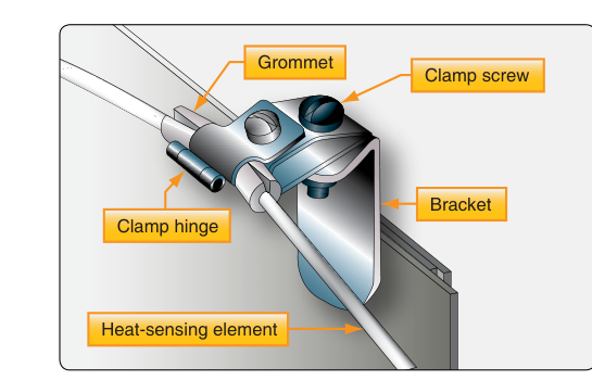
Continuous-loop detector elements require careful visual and functional inspection. The AMT should look for mechanical damage such as kinks, chafing, crushed sections, and corrosion along the entire routed length. Damaged sections must be replaced with approved replacement parts per the manufacturer's instructions—field splicing of sensing elements is generally not permitted. Brackets and clamps securing the loop must be intact and correctly torqued; a loose clamp can allow chafing against structure, eventually breaching the element and causing a false alarm or system inoperability.
Functional testing of continuous-loop systems is accomplished using a heat source (such as a heat gun or hot-air blower) applied to a test section of the loop, or through a dedicated built-in test (BIT) circuit that introduces a test resistance into the loop. The system should alarm within the time specified by the AMM. After testing, the technician must confirm that the alarm cancels correctly and that the loop resistance returns to the normal operating range.
Spot thermal switch detectors can be checked by applying heat directly to the detector body and confirming switch closure at the rated temperature. Ionization smoke detectors are typically tested with calibrated aerosol test sprays designed to simulate combustion particles; never use actual smoke, as residue contaminates the sensing chamber. Photoelectric detectors are tested with a light-obscuring test device or per the specific AMM procedure.
Extinguisher Container Inspections
Halon and replacement-agent containers must be weighed or pressure-checked to verify adequate agent quantity. If the container weight is below the minimum specified on the data plate or in the AMM, the container must be recharged or replaced. Pressure alone is not a reliable indicator of agent quantity because pressure varies with temperature—weight is the definitive check.
Inspect container bodies for dents, corrosion, impact damage, and signs of leakage at valve and tube fittings. Discharge cartridges (squibs) have a service life established by the manufacturer and must be replaced at the specified interval regardless of apparent condition. The AMT must also verify that safety pins and shipping caps are removed before the aircraft is returned to service—an extinguisher with a safety pin installed cannot discharge.
Tubing and distribution lines must be inspected for security, corrosion, dents, and correct routing. Any tubing that passes through areas subject to heat, chafing, or vibration requires additional support and protective sleeving as specified by the AMM.
Regulatory Requirements
The regulatory authority for aircraft fire protection systems spans several areas of 14 CFR and FAA policy documents:
- 14 CFR Part 25 (Subpart D, Fire Protection) — Establishes the type-design certification requirements for transport-category aircraft fire protection systems, including fire zones, flammable fluid shutoffs, and extinguishing agent minimum duration. While Part 25 governs the original design, these standards directly inform maintenance acceptability.
- 14 CFR Part 23 — Contains analogous fire protection certification requirements for normal, utility, and acrobatic category airplanes.
- 14 CFR Part 43, Section 43.13 — Requires that maintenance be performed using methods, techniques, and practices described in the current manufacturer's maintenance manual or other FAA-accepted data, and that each person doing the work uses the proper tools and equipment.
- 14 CFR Part 43, Appendix D — Lists general item groupings, including the engine group and other systems, that must be checked for improper installation, poor general condition, apparent defects, and insecure attachment during a 100-hour or annual inspection; fire detection and extinguishing components are inspected as part of these broader groupings rather than as an explicitly named separate category.
- Airworthiness Directives (ADs) — Many fire protection ADs have been issued to address cracked detector elements, squib replacement intervals, and specific container inspection requirements. All applicable ADs must be consulted before signing off an inspection.
- 14 CFR Part 91, Section 91.409 — Establishes inspection intervals, ensuring that fire protection systems are evaluated at every 100-hour or annual inspection as applicable to the operation.
The FAA's Aviation Maintenance Technician Handbook—Airframe (FAA-H-8083-31) provides detailed guidance on fire protection system inspection and maintenance procedures, including illustrations of system components and wiring diagrams typical of transport and general aviation aircraft.
Key Numbers and Rules
- Continuous-loop detector elements must be inspected for serviceability per the AMM; maximum allowable resistance values are specified by each manufacturer.
- Extinguisher containers below minimum weight (as stated on the data plate) must be replaced or recharged before the aircraft is returned to service.
- Squib (discharge cartridge) service life varies significantly by manufacturer and part number, with no single generally applicable range—always check the AMM and the cartridge data plate for the specific service life.
- A fire warning system test must produce an alarm within the time limit specified in the AMM (commonly within a few seconds of applying the test stimulus).
- Any repair or alteration to a fire protection system must use FAA-approved data; field-fabricated replacement sensing elements are not acceptable without an approved design.
- Per 14 CFR Part 43, Appendix D, fire detection and extinguishing systems are specifically called out as items to be checked during every annual and 100-hour inspection.
Common Test Traps
- Weight vs. pressure for extinguisher serviceability: The FAA written test frequently asks how to determine if an extinguisher container has adequate agent. The correct answer is weight, not pressure alone, because pressure varies with ambient temperature.
- Thermocouple vs. thermal switch operation: Thermocouples respond to rate of temperature rise, not absolute temperature. A thermal switch responds to a specific temperature threshold. Confusing the two is a common error on the AMT knowledge test.
- Continuous-loop false alarms: A fault in the continuous-loop element (such as a kink causing a short) can produce a continuous false alarm rather than an intermittent one. The AMT knowledge test may ask what type of defect causes a false (unwanted) alarm—the answer relates to element damage shorting the circuit.
- Safety pins and shipping caps: A frequent trap is assuming that a fully charged, recently serviced extinguisher is ready for installation. If a safety pin or shipping cap is left in place, the system cannot discharge. Always verify removal per the AMM before sign-off.
- Approved data for repairs: Some candidates assume that because a fire protection component looks simple, generic hardware is acceptable. Any repair to a certificated fire protection system must use manufacturer-approved or FAA-approved data; unauthorized substitutions are an airworthiness violation under 14 CFR Part 43.