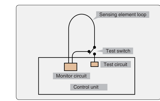
When it comes to protecting aircraft from the devastating consequences of an undetected engine or APU fire, no technology has proven more reliable or more widely adopted than the continuous-loop fire detection system. Unlike spot-type detectors, which sense heat only at discrete points, a continuous-loop system treats the entire length of its sensing element as one long detector—capable of responding to heat anywhere along its run. Two designs dominate aviation practice: the Fenwal system and the Kidde system. Both are covered in depth in FAA guidance for airframe technicians, and questions about their operating principles, fault behavior, and maintenance requirements appear regularly on the AMT Airframe knowledge test.
This article explains how each system works at the engineering level, why continuous-loop detection is the standard for turbine-powered aircraft fire zones, and what specific facts and common misconceptions you need to master before exam day.
What a Continuous-Loop System Is
A continuous-loop fire detection system consists of a sensing element—a small-diameter tube or cable—routed through an entire fire zone in a continuous run, with both ends connected to a control unit. The element is mounted so that it is exposed to the ambient conditions throughout the zone. Because it samples every point along its length rather than a single spot, it responds to localized hot spots, general overheat conditions, and actual flame with much greater coverage and speed than thermistor-type spot detectors alone could provide.
The control unit continuously monitors the electrical characteristics of the loop. When a temperature threshold is exceeded anywhere along the sensing element, the element's properties change, the control unit detects that change, and a warning is triggered in the cockpit—typically a fire warning light and an audible alarm. The loop design also provides a built-in self-test capability: the control unit can verify circuit integrity at any time.
The Fenwal System
The Fenwal continuous-loop system uses a sensing element constructed of a single electrical conductor surrounded by a thermistor-type ceramic core material enclosed in a metal outer tube. The ceramic material has a very high electrical resistance at normal temperatures. As temperature rises toward the alarm threshold, the resistance of the core drops dramatically, allowing more current to flow between the center conductor and the outer tube. The control unit monitors this resistance continuously; when resistance falls to the alarm setpoint, it triggers the warning.
A key characteristic of the Fenwal system is that it is resistant material-based. The ceramic used is a eutectic salt compound whose resistance decreases sharply at elevated temperature. This means the system operates on a resistance-decrease principle: lower resistance equals higher temperature equals alarm condition. Because the ceramic is distributed throughout the entire length of the element, any segment of the loop that reaches the alarm temperature will reduce total loop resistance enough to trigger the warning.
One important maintenance point: an open circuit (a break in the center conductor) in the Fenwal element causes a loss of detection capability and a fault indication, just as it does in the Kidde system—continuity through the loop is required for normal monitoring. However, a short circuit in the Fenwal system—where the center conductor contacts the outer tube directly—will cause a false fire warning, because the control unit interprets the low-resistance path as an overheat condition. Technicians must be alert to chafed elements where the conductor may be in direct contact with the outer sheath.
The Kidde System
The Kidde continuous-loop system takes a different approach. Its sensing element contains two electrical conductors embedded in a thermistor material, all enclosed within an outer tube. In normal operation, the thermistor material keeps the two conductors electrically separated. As temperature rises, the resistance of the thermistor material between the conductors decreases, eventually allowing enough current to flow between them to trigger the alarm.
The Kidde system is sometimes described as an averaging versus a discrete detector: because the two conductors run the full length of the element, a long section of moderate overheat can produce the same alarm as a short section of extreme heat, depending on cumulative resistance change. This makes the system effective for detecting widespread overheat conditions, such as a hot-air bleed-duct leak, as well as localized fires.
Fault behavior in the Kidde system differs importantly from the Fenwal. In the Kidde system:
- An open circuit in either conductor will cause the system to lose detection capability along the portion of the loop beyond the break, and the control unit will typically indicate a fault rather than a false fire warning.
- A short circuit between the two conductors (caused by chafing or damage) will produce a false fire warning, because the control unit sees the same low-resistance signature as a genuine overheat.
This distinction—open vs. short behavior and which triggers false alarms—is a heavily tested topic on the AMT Airframe exam.
Sensing Element Routing and Installation
Regardless of manufacturer, continuous-loop elements must be routed and secured with care. The FAA Airframe Handbook emphasizes these installation principles:
- Elements must be supported at regular intervals to prevent chafing against structure, ducting, or other elements. Unsupported spans can vibrate and eventually cause abrasion damage to the outer sheath.
- Minimum bend radius specifications from the manufacturer must be observed. Kinking the element can crack the internal ceramic or thermistor material, creating a resistance anomaly or an open circuit.
- Elements should not be routed where they will be subjected to excessive vibration without proper cushioned clamps.
- Connectors at both ends must be secure and corrosion-free, since high contact resistance at a connector can mimic the resistance signature of a temperature change and generate nuisance alarms.
- After installation, a loop resistance check is performed using the aircraft's built-in test system or an approved test set to confirm the element resistance falls within the manufacturer's specified range for ambient temperature.
Why Continuous-Loop Systems Are Used in Fire Zones
Turbine engine nacelles, APU compartments, and wing leading-edge bleed-air ducts present fire detection challenges that spot detectors cannot reliably address. Fire or severe overheat can originate anywhere in a large three-dimensional zone. A spot detector placed at only a few locations might not respond for an unacceptably long time if the fire starts between detector heads. The continuous loop, by contrast, provides zone-wide coverage with a single, inspectable element.
Additionally, continuous-loop systems can be set to detect overheat conditions (a lower threshold, indicating a bleed-air leak or pre-fire situation) as well as actual fire temperatures. Some aircraft use separate loops—an overheat loop set to a lower alarm temperature and a fire loop set to a higher threshold—to give the crew graduated warning and more decision time.
Key Numbers and Rules
- The Fenwal system operates on a resistance-decrease principle using a eutectic ceramic core between a center conductor and an outer tube.
- The Kidde system uses two conductors separated by thermistor material inside an outer tube; resistance between the conductors decreases as temperature rises.
- In both systems, a short circuit (conductor-to-tube or conductor-to-conductor) produces a false fire warning.
- An open circuit in either the Fenwal center conductor or the Kidde conductors causes a loss of detection capability and typically a fault indication rather than continued normal alarm function.
- Sensing elements must be inspected for chafing, kinking, and security of mounting at every required inspection interval.
- Resistance checks at ambient temperature must fall within manufacturer-specified limits; values outside limits require element replacement.
- Continuous-loop systems require a functional test using either the aircraft's built-in test (BITE) or an approved heat source applied to the element per the manufacturer's maintenance manual.
Common Test Traps
- Confusing open vs. short circuit behavior: Students frequently reverse which fault produces a false alarm. Remember: a short in either system mimics the low-resistance signature of high temperature and causes a false fire warning. An open circuit typically causes a fault or loss of detection, not a false alarm.
- Mixing up Fenwal and Kidde conductor counts: Fenwal uses one center conductor; Kidde uses two conductors. Exam questions often describe the element construction and ask you to identify the system type.
- Assuming all continuous-loop elements are identical: The ceramic core material (Fenwal) and the thermistor material (Kidde) have different resistance-temperature characteristics. They are not interchangeable, and replacement elements must match the OEM specification exactly.
- Overlooking the effect of connector resistance: A corroded or loose connector introduces resistance into the loop. In the Fenwal system this can mask an alarm condition; in either system it can cause nuisance faults. Always inspect and clean connectors during element maintenance.
- Believing an overheat system and a fire detection system are the same: Some aircraft install dual-threshold loops—a lower-temperature overheat loop and a higher-temperature fire loop. They activate separate annunciations and require separate awareness during troubleshooting.
Mastering the operating principles, fault behavior, and maintenance requirements of Fenwal and Kidde continuous-loop systems gives you both the exam knowledge and the practical foundation to work safely on aircraft fire protection systems. These systems are life-safety equipment; thorough understanding and meticulous maintenance practice are non-negotiable.