Fire protection in aircraft is not optional equipment — it is a critical safety system whose failure can be catastrophic within seconds. Among the earliest and still widely used methods of detecting elevated temperatures or actual combustion in engine nacelles, wheel wells, and cargo compartments is the thermal switch fire detection system. Understanding how these systems are constructed, how they function electrically, and where they are applied is essential knowledge for any Aviation Maintenance Technician (AMT) working on airframe systems.
Thermal switch systems are elegantly simple: they rely on the physical property of certain metals or bimetallic strips to change shape or make contact when heated beyond a design threshold. That mechanical change completes or breaks an electrical circuit, which triggers a warning in the cockpit — usually a red fire warning light, an audible alarm, or both. Their simplicity is a strength; fewer moving parts and no exotic chemistry means the system is robust and maintainable. However, that same simplicity comes with limitations that more advanced detection technologies (like continuous-loop systems) were designed to overcome.
How Thermal Switch Systems Work
At the heart of this system is the thermal switch itself, also called a thermoswitch or heat-sensitive switch. The device contains a bimetallic element — two metals with different coefficients of thermal expansion bonded together. When the ambient temperature rises to the switch's calibrated threshold, the differential expansion of the two metals causes the element to flex and snap closed (or open, depending on design), completing the electrical circuit between the sensing element and the aircraft's warning system.
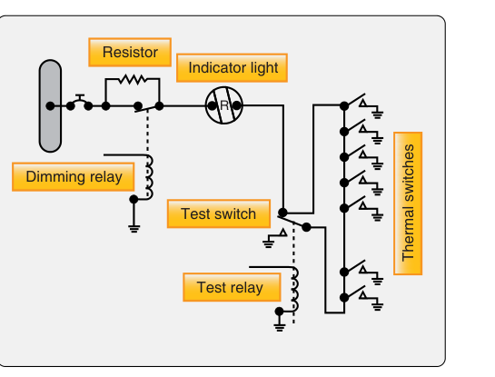
Thermal switches in most installations are wired in parallel with one another across a single warning circuit, so that any one switch closing due to heat is sufficient to complete the circuit and illuminate the fire warning light. You do not need every switch in a zone to activate — just one is enough in this typical arrangement. This design maximizes sensitivity because a localized hot spot anywhere in the monitored zone will be detected as long as a switch is positioned nearby. As with any generalization, technicians should always verify the actual wiring configuration against the specific aircraft's maintenance manual and wiring diagrams rather than assume a universal arrangement.
The warning circuit itself is typically connected to a relay or directly to a cockpit annunciator panel. When the circuit is completed by a closing thermal switch, current flows through the relay coil, which energizes the warning light and horn. Some installations use a test circuit that allows the flight crew or maintenance technician to verify the integrity of the wiring and switches without actually heating the sensors. A properly functioning test will illuminate the warning light, confirming the bulb, wiring, and relay are all serviceable.
Single-Loop vs. Dual-Loop Arrangements
In some aircraft installations, thermal switch systems are arranged in a single loop — one set of switches monitoring a zone. More critical applications, particularly on transport-category aircraft, may employ two independent loops for the same zone. On many dual-loop designs, either loop detecting heat is sufficient to trigger the fire warning (OR logic), which maximizes detection reliability — a fire must not go undetected because of a single loop malfunction. Some continuous-loop and fire-detection-card designs use signal agreement between loops as a technique to help reduce nuisance or false warnings, but this is not the same as requiring both loops to agree before any warning is annunciated. The specific logic implemented depends on the aircraft designer's balance between nuisance alarms and detection reliability, and technicians should consult the applicable maintenance manual for the exact logic used on a given installation.
System Components
A complete thermal switch fire detection system includes several identifiable components that the AMT must be able to inspect, test, and replace:
- Thermal switches (thermoswitches): The primary sensing elements, positioned throughout the protected zone at intervals determined by engineering analysis. Each switch is rated for a specific activation temperature.
- Warning light(s): Typically red, located on the cockpit fire panel or annunciator panel. These lights indicate a fire or overheat condition in a specific zone.
- Audible alarm: A horn or bell that sounds simultaneously with the warning light, ensuring the crew cannot miss the alert.
- Test switch: Allows ground testing of the circuit continuity without exposing the sensors to heat.
- Relay or controller: Interprets the signal from the switches and energizes the warning devices.
- Wiring harness: Must be routed away from heat sources to prevent false alarms from harness degradation, yet close enough to the monitored zone to carry signals reliably.
Where Thermal Switch Systems Are Used
Thermal switches are most commonly found in locations where discrete, spot monitoring is adequate. Typical installations include wheel wells (to detect brake overheat or a wheel-well fire after gear retraction), cargo and baggage compartments, and auxiliary power unit (APU) compartments. They have also historically been used in reciprocating engine nacelles on smaller aircraft, though many modern turbine-powered aircraft with higher performance requirements use continuous-loop systems in the main engine nacelles instead.
The reason thermal switches are preferred in some of these locations over continuous-loop systems is economic and functional: wheel wells and cargo compartments have well-defined geometries, tend to have lower-temperature thresholds to monitor, and do not experience the enormous heat gradients found in a turbine engine nacelle. A modest number of thermal switches can reliably cover these zones without the complexity of a continuous sensing element.
Why It Matters — Safety and Airworthiness
A malfunctioning fire detection system is not a minor discrepancy. Under 14 CFR Part 25 (for transport-category aircraft), §25.1203 requires fire-detector systems installed in designated fire zones to provide prompt detection of fires, meeting specific performance criteria for detection speed, resistance to false or nuisance warnings, and clear indication to the crew. The FAA's airworthiness standards require that detection systems be reliable, have a minimum of false alarms, and be testable. These same principles cascade into the maintenance requirements that AMTs work under daily.
If a thermal switch fails in the open position, it will never close regardless of temperature — the fire warning will not occur when needed. This is a dangerous hidden failure. If it fails in the closed position, the warning circuit is permanently completed, and the cockpit will show a continuous fire warning — a nuisance alarm that could cause the crew to disregard genuine warnings in the future, or lead to unnecessary engine shutdowns. Either failure mode demands prompt maintenance action.
Regular testing using the aircraft's built-in test circuit catches closed-circuit faults readily, since the test relies on current flowing through the switches. Open-circuit faults in individual switches can be harder to detect by test alone and may require individual switch resistance or continuity checks during scheduled maintenance.
Key Numbers and Rules
- Parallel wiring: In most installations, thermal switches are wired in parallel — any single switch closing completes the circuit and triggers the warning. Always confirm against the specific aircraft's wiring diagrams.
- Activation temperature: Varies by installation and zone, but switches are factory-calibrated. Never substitute a switch with an incorrect temperature rating.
- Test circuit: Must illuminate all associated warning lights when activated; failure of a warning light during test indicates a bulb or wiring fault, not necessarily a switch fault.
- Inspection intervals: Follow the aircraft manufacturer's maintenance manual (MM) and Instructions for Continued Airworthiness (ICA). Thermal switches are typically inspected for security of attachment, evidence of corrosion, and proper gap or contact condition.
- False alarm risk: Switches located too close to hot components (brakes, exhausts) not in the fire zone can trigger nuisance alarms; always verify switch placement per the MM.
- Replacement: Thermal switches are generally not field-repairable — replace with the exact part number specified in the Illustrated Parts Catalog (IPC).
Common Test Traps
- Series vs. parallel confusion: Students sometimes assume thermal switches are wired in series because they are multiple sensors on one circuit. In most designs they are wired in parallel — this is a frequently tested point. Series wiring would require ALL switches to close before an alarm triggers; parallel requires only ONE.
- Open vs. closed failure consequences: Confusing which failure mode causes which symptom is a common error. An open failure = no alarm when fire exists (the dangerous mode). A closed failure = continuous false alarm.
- Thermal switch vs. continuous-loop: Thermal switch systems provide spot detection; continuous-loop systems provide linear, zone-wide detection. They are not interchangeable, and the test may ask you to identify which system type is described by a given characteristic.
- Test circuit purpose: The test circuit checks electrical continuity of the warning circuit (lights, wiring, relay), NOT the calibration or heat-response of the individual thermal switches. Passing the test does not certify that a switch will close at the correct temperature.
- Replacement parts: Installing a thermal switch rated for the wrong activation temperature — even if physically identical — is an airworthiness violation. Always cross-reference the part number before installation.
Thermal switch fire detection systems represent one of the most foundational technologies in aircraft fire protection. Their parallel-circuit architecture, bimetallic sensing elements, and straightforward cockpit interface make them a reliable and maintainable solution for spot-detection applications. For the AMT, mastering both the theory and the practical inspection and troubleshooting of these systems is a core competency that directly supports the safety of every flight.