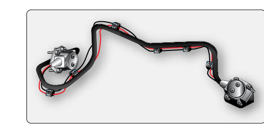
Among the several fire detection technologies approved for use on transport-category and turbine-powered aircraft, the pneumatic pressure fire detection system — commonly associated with the trade names Lindberg (a Kidde product line) and Systron-Donner — occupies a well-respected place because of its simplicity, reliability, and self-monitoring capability. Unlike spot-detector systems that rely on individual thermal switches or thermocouples at discrete points, the pneumatic system routes a continuous sensing tube throughout the protected zone, so every inch of that tube is a potential alarm point. Understanding how this system is built, how it triggers an alarm, and how it monitors its own integrity is essential knowledge for AMT candidates preparing for the FAA Airframe certification.
The FAA Aircraft Maintenance Technician Handbook — Airframe (FAA-H-8083-31) covers fire protection systems in detail and describes the pneumatic continuous-loop detector as one of the most reliable designs available for powerplant nacelles, APU compartments, and cargo areas. The following article walks through the full operating principle, real-world significance, key specifications, and the traps that appear on the knowledge test.
How the Pneumatic Pressure System Works
The heart of the system is a small-diameter, stainless-steel tube — sometimes called the sensing element or responder tube — that is routed around the entire fire zone in a continuous loop. The tube is hermetically sealed and filled with a core material and an inert gas mixture. The specific fill depends on the manufacturer's design, but in both the Lindberg and Systron-Donner versions the physics are the same: when the tube is heated, the internal gas pressure rises, and that pressure rise is used to actuate an alarm switch.
More precisely, two separate pressure-sensitive phenomena work together inside a well-designed pneumatic detector tube:
- Average overheat detection. The gas fill throughout the length of the tube obeys the ideal gas law — pressure is proportional to absolute temperature. If the entire zone experiences a gradual temperature rise (such as a hot-air duct leak warming the whole nacelle), the bulk gas pressure climbs steadily until it crosses the alarm threshold.
- Discrete fire detection. A core material inside the tube — sometimes a salt compound or similar absorbent — is engineered to release additional gas rapidly at a specific, higher temperature that represents a true fire condition. This creates a sharp pressure spike even if only a small portion of the tube is affected, such as a localized flame touching just a few inches of tubing.
At one end of the sensing tube sits a responder unit (sometimes called the control unit or pressure switch assembly). This unit contains a sealed reference chamber and a differential pressure switch. Under normal conditions the reference chamber and the sensing tube are balanced. When the tube pressure rises — either by average overheat or by discrete fire — the differential pressure switch closes, completing an electrical circuit to the cockpit fire-warning system. The alarm sounds and the fire-warning light illuminates.
Continuous Integrity Monitoring — the Key Advantage
What sets pneumatic systems apart from simple spot detectors is automatic loop integrity checking. The system continuously monitors for two failure conditions that would render a spot-detector system silently inoperative:
- Loss of gas pressure (tube rupture or leak). If the sensing tube develops a crack, puncture, or fitting leak, the internal gas escapes and the tube pressure falls below a preset low-pressure threshold. The responder unit detects this drop and sends a fault signal to the cockpit — a separate indicator that tells the crew the detector is unserviceable, not that there is a fire. This is critically different from a spot detector, which simply stops working with no indication when it fails open.
- Electrical continuity of the alarm circuit. The responder unit also monitors the electrical wiring between itself and the cockpit indicators, so a broken wire generates a fault rather than a silent failure.
This dual-monitoring philosophy is a design characteristic built into certain continuous-loop systems, such as the Kidde/Lindberg and Systron-Donner designs. While 14 CFR Part 25, Subpart F (including §25.1203) requires transport-category fire detection systems to be reliable and to provide rapid, accurate detection, the regulatory text does not explicitly mandate a self-diagnostic failure-indication capability — the fault-monitoring feature is an engineering enhancement adopted by these designs rather than a specific Part 25 requirement. Even so, it is a valuable fail-safe characteristic: a failed system tells you it has failed.
Physical Construction and Installation Details
The sensing tube is typically stainless steel with an outside diameter of about 1/8 inch (approximately 3 mm). It is routed with support clamps at intervals specified by the aircraft manufacturer, and care is taken to avoid sharp bends that could kink the tube and restrict the internal gas column or create a stress-concentration point susceptible to cracking. Minimum bend radii are given in the aircraft's maintenance manual and the system manufacturer's data — never exceed the minimum or the tube may fail prematurely.
Connections at the responder end use compression fittings or flare fittings appropriate for the pressure and temperature environment. Any fitting leak is, by design, self-announcing: the resulting pressure drop trips the fault indication. The tube is also electrically bonded to the aircraft structure at intervals to prevent static buildup and to satisfy the aircraft's lightning/EMI bonding requirements.
Installation requires that the sensing element be kept away from abrasion points — areas where vibrating structure or wiring bundles could chafe the tube over time. Chafing that produces even a pinhole leak will cause nuisance fault indications and requires tube replacement or approved repair per the manufacturer's data.
Why It Matters — Safety and Regulatory Significance
Transport-category powerplant nacelles, APU bays, and certain cargo compartments must be equipped with fire detection systems that meet the standards of 14 CFR Part 25, Subpart F (including §§25.851, 25.854, 25.858, and 25.1203). Part 26 addresses continued airworthiness and retrofit requirements for certain older transport-category aircraft and is not itself the primary fire-detection design standard. The pneumatic continuous-loop design satisfies the Part 25 requirements in several important ways. First, because the sensing element has no moving parts, no electrical contacts, and no semiconductor junctions inside the hot zone, it is inherently resistant to the vibration, moisture, fuel vapors, and extreme temperature cycles that rapidly degrade other sensor technologies. Second, the combination of average-overheat and discrete-fire detection means the system responds correctly to both smoldering, diffuse heat events and to fast, high-intensity fires. Third, the self-monitoring feature reduces the probability that a crew will unknowingly fly with an inoperative fire detection system.
From a maintenance standpoint, the AMT's primary ongoing tasks are visual inspection of the tube for kinks, chafing, and security of clamps; leak-checking fittings; verifying the responder unit's electrical connections; and functional testing per the aircraft maintenance manual. Because the system announces its own failures, a technician performing a pre-return-to-service functional test can distinguish a normal alarm response from a fault signal with confidence.
Key Numbers and Rules
- Two detection modes: average overheat (bulk gas pressure rise) and discrete fire (core material gas release at localized high temperature).
- Sensing tube OD: approximately 1/8 inch stainless steel — exact dimensions vary by aircraft type; always reference the aircraft maintenance manual.
- Fault indication on pressure loss: a drop in tube pressure below the low-pressure threshold produces a fault (not a fire) warning — this is the self-monitoring feature.
- No electrical components in the hot zone: only the gas-filled metal tube is exposed to the fire zone; all switching occurs in the responder unit, which is typically mounted outside the highest-temperature area.
- Regulatory basis: 14 CFR Part 25, Subpart F (fire protection, e.g., §§25.851, 25.854, 25.858, 25.1203) for transport-category aircraft; aircraft-specific maintenance per the approved maintenance manual and/or the system manufacturer's Component Maintenance Manual (CMM).
- Bend radius: must meet manufacturer minimums — typically several times the tube OD; kinking is a cause for tube rejection.
- Responder unit location: mounted in a cooler, accessible location with the sensing tube routed into the hot zone; the unit contains both the differential pressure switch and the low-pressure fault switch.
Common Test Traps
- Fault vs. fire alarm confusion. A tube rupture or gas leak does NOT produce a fire warning — it produces a fault or integrity warning. Test questions often describe a low-pressure condition and ask what indication appears; the answer is a fault indication, not a fire alarm.
- Confusing pneumatic with thermocouple or thermistor systems. Thermocouple systems operate on rate-of-temperature-rise and generate a small EMF; pneumatic systems operate on absolute pressure change. They are fundamentally different. Test items sometimes intermix characteristics — read carefully.
- Assuming spot-detector limitations apply here. The pneumatic loop detects fires anywhere along its entire length, not just at specific points. Questions that ask about the advantage of continuous-loop systems versus spot detectors are testing this distinction.
- Tube repair misconceptions. Not all kinks or dents are field-repairable. Unless the manufacturer's CMM explicitly authorizes a repair method, a damaged tube section must be replaced. The test may present a scenario where the tempting but wrong answer is to straighten a kinked tube with pliers and return it to service.
- Ignoring the integrity monitoring when testing. During a functional test of the fire warning circuit, technicians must verify both the fire alarm response AND the fault indication response (by simulating a pressure loss). Testing only the alarm half leaves the fault circuit unverified — a common maintenance shortcut that the test penalizes.
Mastering the pneumatic pressure fire detection system means understanding that its elegance comes from combining physics (the gas law), smart engineering (the two-mode detection core), and regulatory foresight (mandatory self-monitoring). An AMT who understands these principles can troubleshoot nuisance alarms, distinguish faults from fires, and confidently inspect and functionally test the system — all core competencies the FAA Airframe knowledge test and oral exam will probe.