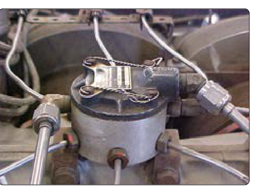
In a reciprocating or turbine aircraft engine, the fuel manifold and distribution system is the network of components that takes metered fuel from the fuel control unit (or carburetor, in simpler systems) and delivers it evenly to every cylinder or combustion chamber. On a fuel-injected reciprocating engine, this means a fuel manifold valve — sometimes called a fuel distributor or spider — and a set of injector lines leading to individual fuel-injection nozzles. On turbine engines, the manifold feeds fuel nozzles that atomize and spray fuel into the combustion section. In either case, an improperly functioning manifold or clogged distribution line can cause rough running, uneven power, hot-section damage, or a dangerous in-flight engine failure. For the AMT Powerplant technician, thorough, methodical inspection of this system is a core airworthiness responsibility.
This article walks through the purpose of each major component, the inspection procedures specified in FAA guidance, the defects you are most likely to find, and the practical standards for determining whether a component is serviceable or must be replaced. Everything here is grounded in the FAA Aviation Maintenance Handbook — Powerplant (FAA-H-8083-32) and the principles in FAA-H-8083-30 (General) as they apply to fuel system maintenance.
System Architecture and Component Roles
Understanding inspection starts with understanding what each part does. On a fuel-injected reciprocating engine such as the Continental or Lycoming variants common in general aviation, the fuel flow path after the engine-driven fuel pump is: fuel control unit (or fuel-injection servo) → fuel manifold valve → individual injection lines → fuel injection nozzles at each cylinder. The fuel manifold valve is a spring-loaded diaphragm device. At idle or shutdown, the diaphragm keeps outlets closed so fuel does not dribble into cylinders and cause hydraulic lock. When fuel pressure rises to the operating threshold, the diaphragm lifts and opens all outlets simultaneously, delivering an equal head of pressure to each injector line. This equal-pressure starting point is what makes distribution uniform across all cylinders.
The individual injector lines are small-diameter stainless steel or aluminum alloy tubes, each precisely the same length and inside diameter from manifold to nozzle. This matched geometry is intentional — any difference in line length or restriction changes the fuel quantity delivered to that cylinder, disrupting the engine's mixture balance. The fuel injection nozzles themselves are calibrated orifices that atomize fuel as it enters the intake port. Each nozzle has an air bleed that vents to the atmosphere and helps prevent post-shutdown fuel dribble. On turbine engines, the manifold is a ring-shaped or branched tube surrounding the combustion section, feeding either simplex or duplex fuel nozzles; the inspection principles for leaks, security, and nozzle condition remain the same.
Pre-Inspection Preparation
Before touching any fuel system component, the technician must follow all applicable safety precautions: ensure the ignition is off and the mixture is at idle cutoff, relieve any residual fuel pressure by cracking a fitting (using appropriate personal protective equipment and fire-prevention measures), and position fire extinguishing equipment nearby. Consult the applicable aircraft maintenance manual (AMM) and engine manufacturer's overhaul manual for the specific torque values, sealant specifications, and inspection intervals that apply. FAA-H-8083-32 emphasizes that manufacturer data always governs; the handbook provides principles, not aircraft-specific limits.
Gather the proper tools: calibrated torque wrench, bright inspection light, magnifying glass or borescope for tight areas, cleaning solvents approved for fuel systems, and any special fixtures called out in the AMM. Have replacement O-rings, gaskets, and backup rings on hand — whether a disturbed seal must be replaced rather than reused depends on the fitting type and the manufacturer's specific instructions, so always check the applicable AMM before reusing a seal.
Inspection Procedures
Visual Inspection for Leaks and Staining
Begin with a thorough external visual inspection of all manifold fittings, line connections, and nozzle seats. Fuel staining — a dark, often wet discoloration — is the primary indicator of a seeping connection. Even a very small fuel leak in the engine compartment is an airworthiness hazard, not just an inconvenience, because engine compartment temperatures and ignition sources are always present. Look carefully at:
- The manifold body itself for cracks, corrosion pitting, or impact damage.
- Every B-nut or threaded fitting for signs of weeping fuel or blue-green corrosion products indicating a chronic small leak.
- Each injector line along its entire length for chafing, kinking, dents, or contact with hot engine surfaces such as exhaust components.
- The nozzle-to-cylinder head fittings for staining or thread damage.
Any fitting that shows staining must be cleaned, the source of the leak identified, and the defect corrected before the aircraft returns to service. Do not simply re-torque a leaking B-nut without inspecting the flare, ferrule, and mating seat — re-torquing a damaged flare almost always fails again.
Manifold Valve Inspection
The fuel manifold valve (distributor valve) is a precision diaphragm device. Inspect the exterior for cracks and corrosion. Check that the vent port — which allows the underside of the diaphragm to breathe — is open and unobstructed. A blocked vent can cause the diaphragm to become pressure-bound, preventing the valve from opening or closing correctly, and will manifest as an inconsistent idle or difficulty achieving even fuel flow across cylinders. If the maintenance manual calls for removal and bench testing of the manifold valve, test the opening pressure against the manufacturer's specification. A diaphragm that opens too early causes fuel dribble; one that opens too late causes hard starting or lean operation at low power.
Injector Line Inspection
Each injector line must be inspected for chafing — the most common defect in service. Lines that contact engine mounts, baffles, or other lines will eventually wear through, creating a fuel leak under pressure. FAA-H-8083-32 notes that fuel lines must be supported and clamped so they cannot vibrate or contact adjacent structures. Check clamps for security and condition; a corroded or overtightened clamp can itself cause a chafe point. Inspect flared ends under magnification for cracks radiating from the flare cone — these are common if the line has been over-torqued or repeatedly removed and reinstalled. A cracked flare cannot be re-flared in place and the line must be replaced.
Lines must also be inspected for internal cleanliness if removed. Flush the lines with fresh, clean fuel or a suitable solvent and inspect the effluent. Metallic particles in a fuel line indicate upstream component wear; contamination in an injector line can clog the calibrated nozzle orifice and lean out that cylinder.
Fuel Injection Nozzle Inspection and Cleaning
Fuel injection nozzles clog gradually from fuel varnish deposits or particulate contamination. A partially clogged nozzle leans that cylinder, which elevates its exhaust gas temperature (EGT) and can lead to detonation or valve burning. Nozzles are removed periodically per the engine manufacturer's schedule, cleaned in an approved solvent, and flow-tested or at minimum visually inspected and blown clear with filtered, dry compressed air. Never use wire or metal picks to clear a nozzle orifice — the calibrated hole is precision-sized and any enlargement permanently changes the fuel flow. Replace nozzles that cannot be cleaned to the manufacturer's flow specification.
Inspect the air-bleed hole in each nozzle — this small port prevents post-shutdown dribble by allowing air into the nozzle when fuel pressure drops. A blocked air bleed causes fuel to continue dribbling into the intake port after shutdown, wetting the cylinder and increasing the risk of hydraulic lock on the next start.
Why This Inspection Matters
Uneven fuel distribution across cylinders is insidious because it can be difficult to detect without engine monitor data. A pilot may simply notice rough running or reduced power. Behind that symptom can be an over-lean cylinder approaching detonation or an over-rich cylinder fouling its spark plugs. The AMT's role is to catch these conditions before they degrade safety. Additionally, any fuel leak in a certificated aircraft makes the aircraft unairworthy under 14 CFR Part 43 and Part 91 until corrected — the pilot in command and the maintaining technician both share responsibility for airworthiness.
Key Numbers and Rules
- Fuel manifold valve opening pressure: specified by the engine manufacturer; always verify against the current AMM — values vary by engine model.
- B-nut torque: specified in the AMM; typical aluminum AN fittings are torqued far lower than steel — over-torquing cracks the flare.
- Line replacement: FAA-H-8083-32 does not set a universal numeric wall-thickness threshold for chafe or damage; any kink, crack, or chafe must be evaluated against the specific limits in the aircraft/engine manufacturer's AMM or ICA, and replaced if those limits are exceeded.
- Nozzle cleaning intervals: set by the specific engine manufacturer's Instructions for Continued Airworthiness (ICA) or maintenance manual — there is no single FAA-mandated interval that applies to all engines.
- Leak standard: no fuel leaks are acceptable in a certificated aircraft engine fuel system — even seeping fittings make the aircraft unairworthy.
- Return-to-service record: all maintenance on fuel system components must be documented in the aircraft maintenance records per 14 CFR §43.9.
Common Test Traps
- Confusing the manifold valve's vent with a leak: the vent port normally expels a tiny amount of fuel or vapor during shutdown; this is by design. However, continuous flow from the vent indicates a failed diaphragm, not normal operation.
- Re-torquing a leaking B-nut without inspecting the flare: the test will ask you to identify the correct next step after discovering a leaking fitting. Inspection of the flare and seat — not simply re-torquing — is the correct answer.
- Using metal tools to clear nozzle orifices: the test specifically targets this unsafe practice. Only approved solvents and filtered compressed air are acceptable.
- Assuming equal line length is merely convenient: the equal length and equal diameter of injector lines is an engineering requirement for balanced fuel distribution, not optional.
- Overlooking chafing between lines and exhaust components: a fuel line contacting an exhaust stack is an immediate fire hazard and airworthiness discrepancy, regardless of how minor the contact appears visually.