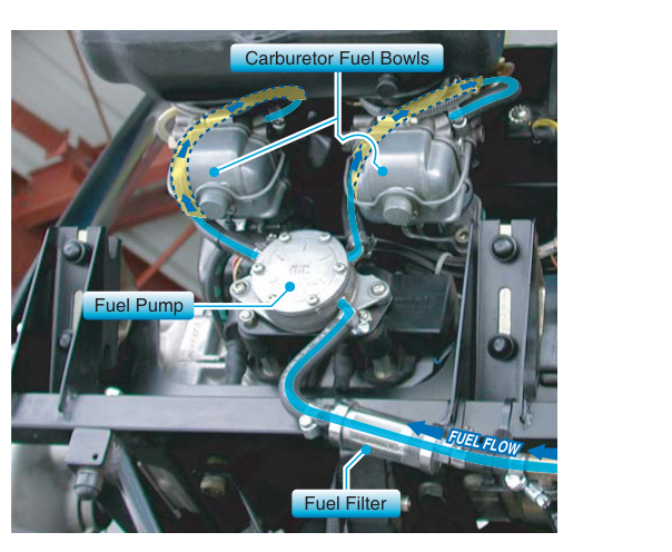
The carburetor is one of aviation's oldest and most elegantly simple fuel-metering devices, yet it demands precision engineering at every turn. At the heart of any float-type carburetor — the design found on the majority of certificated light aircraft piston engines — is the float bowl, a small fuel reservoir that makes consistent mixture control possible across a wide range of altitudes, airspeeds, and power settings. Understanding how the float bowl fills, stabilizes, and meters fuel is not just exam knowledge; it is the foundation for diagnosing flooding, lean surge, vapor lock, carb ice, and a host of other fuel-system squawks that show up in the field.
This article walks through float bowl operation from first principles: how the float mechanism maintains a constant fuel level, how that level interacts with the main discharge nozzle, and how the various metering circuits — idle, main, and mixture — draw on that stored fuel to deliver the right air-fuel ratio at every throttle position.
The Float Mechanism: Maintaining a Constant Fuel Level
Fuel arrives at the carburetor from the aircraft fuel system under low positive pressure — typically provided by an engine-driven fuel pump, a boost pump, or gravity, depending on the installation. That fuel enters the float bowl through an inlet fitting and passes a needle valve and seat assembly before pooling in the bowl itself.
The float — historically made of thin brass or cork, today often a sealed plastic or composite pontoon — rests on the surface of the fuel in the bowl. As fuel fills the bowl and the level rises, the float rises with it. A lever arm connects the float to the needle valve; when the float reaches the design level, it pushes the needle firmly into its seat, shutting off incoming fuel. When the engine draws fuel out of the bowl through the discharge nozzle, the level drops, the float descends, the needle unseats, and fresh fuel flows in. This continuous feedback loop keeps the fuel surface at a nearly constant height relative to the main discharge nozzle — a relationship that is absolutely critical to mixture accuracy.
The design fuel level is calibrated at the factory. Most float-type carburetors are adjusted so that the fuel surface sits slightly below the lip of the main discharge nozzle — typically only a small fraction of an inch below the nozzle outlet, commonly on the order of 1/8 to 3/16 inch, depending on the specific design. This small difference in height (called fuel head) prevents raw fuel from dribbling out of the nozzle when the engine is not running, while still allowing venturi suction to draw fuel readily once the engine is running. If the fuel level climbs too high — often called an overly rich float setting — fuel can siphon out of the nozzle at idle and cause flooding or an overly rich mixture. If it sits too low, the engine may run lean, hesitate on acceleration, or fail to restart after a hot soak.
The Main Metering System and the Venturi
With the float bowl maintaining a stable fuel level, the carburetor can use a beautifully simple physical principle to meter fuel: the venturi effect. Air flowing through the carburetor throat accelerates through a narrowed section (the venturi), and by Bernoulli's principle that acceleration causes a drop in local static pressure. The main discharge nozzle opens into the carburetor barrel at or near the point of lowest pressure — the venturi throat.
Because the fuel in the float bowl is exposed to ambient (higher) pressure through a small vent, there is now a pressure differential between the fuel surface and the discharge nozzle outlet. That differential pushes fuel up through the main metering jet — a precisely sized orifice that is the primary determinant of the engine's fuel flow at cruise and high-power settings. The jet's calibrated hole size creates a specific restriction; for a given pressure drop across it (which increases with throttle opening and airspeed through the venturi), a predictable mass of fuel flows. This is why main metering jets are specified by a drill-size number and are not interchangeable between carburetor models without re-certification of the fuel system.
Just upstream of the discharge nozzle tip, many designs incorporate an emulsion tube or air-bleed passage. This admits a small, metered amount of air into the fuel stream as it rises toward the nozzle, breaking the fuel into a fine emulsion. The emulsified fuel atomizes more readily once it exits into the high-velocity airstream, improving mixture homogeneity especially at mid-range throttle settings.
The Idle Circuit
At low throttle, the venturi sees so little airflow that pressure drop at the main nozzle is insufficient to draw fuel. Instead, fuel is routed through the idle circuit: a separate passage that draws fuel from the float bowl through its own restricted jet, then discharges through one or two small ports located just downstream of the throttle plate — right where airflow velocity (and therefore pressure drop) is highest when the throttle is barely cracked open. As the throttle opens progressively, idle circuit discharge tapers off and the main nozzle takes over; a correctly calibrated transition means no lean stumble or rich surge during acceleration. The idle mixture needle — an adjustable screw that varies the effective restriction of the idle discharge port — allows a mechanic to fine-tune the idle air-fuel ratio. Adjustment procedures are specified in the manufacturer's overhaul or maintenance manual and typically involve setting idle RPM, then slowly leaning the mixture until RPM peaks slightly before leaning further causes a drop.
The Mixture Control
Most aircraft carburetors include a mixture control that the pilot manipulates from the cockpit. In the most common design — the back-suction or altitude mixture control — a valve routes a portion of the low-pressure venturi signal back to the float bowl vent. By reducing the pressure differential between the bowl and the discharge nozzle, this decreases fuel flow, leaning the mixture. At full rich the bowl vent is open to atmospheric pressure (maximum differential, richest mixture); at idle cutoff the vent is fully connected to venturi suction (differential collapses to near zero, fuel flow stops, engine shuts down cleanly without hydraulic lock). An alternative design uses a needle valve in the main jet passage itself, physically restricting fuel flow as the mixture control is moved toward lean.
Why Float Bowl Operation Matters for Safety and Maintenance
Precise float-bowl fuel level is not an academic concern. A float that has developed a pinhole leak will fill with fuel, become heavy, and sink — holding the needle valve open. The result is a continuously flooding carburetor: raw fuel overflows the bowl vent or floods the induction system, creating an extreme fire hazard and potential engine stoppage. Conversely, a float that has collapsed or a needle valve seat that has worn to a ridge may allow the level to drop unpredictably, leaning the mixture at the worst possible moments.
Carb ice is another float-bowl-adjacent concern. As moisture in induction air freezes on the venturi walls and throttle plate, the effective venturi area decreases. This shifts the pressure differential in ways that can richen the mixture and ultimately block airflow entirely. The pilot's tool — carburetor heat — uses exhaust-heated air to melt ice, but that hot air is less dense, which also temporarily richens the mixture and reduces power before the ice clears.
Key Numbers and Rules
- Float bowl fuel level is set slightly below the main discharge nozzle outlet; the exact specification (in fractions of an inch) is found in the manufacturer's overhaul manual for each carburetor model.
- Needle valve seat condition is inspected at overhaul; a worn or pitted seat allows fuel seepage and rising fuel level.
- Main metering jet size is designated by a drill-number and must match the carburetor model's specification; substitution requires FAA approval.
- Idle mixture adjustment is performed with the engine at normal operating temperature; the target is typically the highest stable idle RPM achievable before the mixture becomes too lean to sustain combustion.
- Float material must be inspected for fuel absorption, cracks, or puncture; a brass float is shaken near the ear — fuel sloshing inside indicates a leak.
- Float weight and buoyancy determine the equilibrium fuel level; manufacturers specify the float weight limit, and a float outside tolerance must be replaced.
- Mixture control at idle cutoff stops fuel flow without creating a hydraulic fuel slug in the cylinder — the preferred shutdown method for most carbureted aircraft engines.
Common Test Traps
- Confusing high fuel level with lean mixture. Students sometimes assume more fuel in the bowl means leaner operation. In fact, a fuel level that is too high moves the surface closer to (or above) the nozzle outlet, which richens or floods the mixture — not leans it.
- Assuming the main jet meters fuel at idle. At closed or near-closed throttle, the idle circuit does the metering work; the main nozzle sees insufficient pressure differential to function effectively until the throttle opens sufficiently.
- Misidentifying the purpose of carburetor heat. Carb heat is not an enrichment device; it melts ice by raising induction air temperature. The temporary enrichment effect is a side effect of using less-dense hot air, not the goal.
- Overlooking the float vent in back-suction mixture controls. The back-suction system leans the mixture by reducing — not increasing — pressure in the float bowl. Students sometimes reverse the direction of the pressure relationship on written test questions.
- Thinking idle cutoff starves the engine of air. Idle cutoff stops fuel flow, not airflow. The engine dies from fuel starvation, not suffocation, which is why cylinders are not damaged by excess fuel during shutdown.