Every certificated aircraft engine that burns liquid fuel needs a reliable way to move that fuel from the tank to the combustion chamber at the right pressure and flow rate, at every altitude and power setting the aircraft is expected to fly. The engine-driven fuel pump (EDFP) is the primary device that accomplishes this task on the vast majority of piston and turbine powerplants. Unlike an electric boost pump — which is a backup or priming device — the engine-driven pump is mechanically coupled to the engine's accessory drive and spins whenever the engine spins. That mechanical dependency is both its greatest strength and its most important vulnerability, and every AMT candidate needs to understand both sides of that equation.
This article covers the fundamental design types used in general aviation and turbine aircraft, how each type works on a thermodynamic and mechanical level, how the system behaves in normal operation, and — critically — what failure looks like and why.
Types of Engine-Driven Fuel Pumps
Vane-Type (Rotary-Vane) Pump
The vane-type pump is the most common EDFP found on piston aircraft engines. Its rotating element consists of a slotted rotor mounted eccentrically inside a circular housing. Spring-loaded or centrifugally extended vanes slide outward in the rotor slots and maintain contact with the housing wall. As the rotor turns, the vanes sweep out crescent-shaped chambers between themselves, the rotor, and the housing. On the intake side of the pump, these chambers grow larger, drawing fuel in from the tank through the inlet port. As rotation continues, the chambers shrink on the outlet side, squeezing fuel out through the discharge port at elevated pressure.
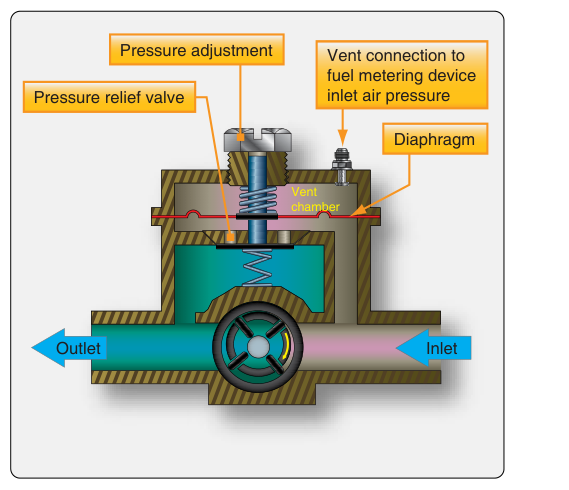
Because the pump output is continuous and essentially fixed by rotor speed, a relief valve is built into the pump body or the adjacent fuel system plumbing. This spring-loaded valve opens when outlet pressure exceeds a calibrated limit, routing excess fuel back to the inlet side (or to the tank return line). The relief valve is what prevents dangerously high pressure from reaching the carburetor or fuel-injection servo at high engine RPM.
Gear-Type Pump
Some older or heavier-duty piston engines, and many turbine accessory gearbox installations, use a gear-type pump. Two meshing spur gears rotate inside a close-tolerance housing. Fuel is carried around the outside of each gear in the spaces between the teeth and the housing, from the inlet side to the outlet side. As the teeth mesh in the center, they block reverse flow and force fuel out the discharge port. Gear pumps are simple, robust, and tolerant of contamination, but they share the same fundamental characteristic as vane pumps: output pressure rises steeply with any resistance to flow, so a relief valve is equally essential.
Centrifugal Pump (Turbine-Engine Boost Stage)
Many turbine-engine fuel systems use a centrifugal (boost) stage upstream of a high-pressure positive-displacement pump. The centrifugal stage raises fuel pressure enough to prevent vapor lock and cavitation in the high-pressure pump. Centrifugal pumps are not positive displacement — their output pressure depends heavily on rotor speed and back-pressure — so they are not used alone as the primary metering device. You will encounter them primarily in the low-pressure portion of turbofan and turboprop fuel systems.
Diaphragm Pump
Many Continental and Lycoming piston engine installations use a mechanically driven diaphragm-type fuel pump, where a rocker arm actuated by an eccentric cam on the accessory drive flexes a diaphragm to create a reciprocating pumping action, with check valves controlling inlet and outlet flow. Far from being an obsolete curiosity, this diaphragm design has long been a standard, widely used engine-driven fuel pump on many certificated carbureted Continental and Lycoming engines, and it remains a common design an AMT candidate should know thoroughly.
How the EDFP Integrates with the Fuel System
On a typical fuel-injected piston engine, the engine-driven pump draws fuel from the selector valve (through a strainer) and delivers it to the fuel-injection servo or flow divider at a pressure typically in a lower and narrower range — generally on the order of 15 to 30-some PSI depending on the engine model — always consult the applicable engine manufacturer's data for precise values. A bypass provision within the fuel injection system's plumbing allows the electric boost pump to push fuel directly to the injection system if the engine-driven pump fails, because a check valve opens when inlet pressure from the boost pump exceeds the back pressure at the EDFP outlet. The specific location and implementation of this bypass varies by manufacturer and is not a universal feature of every vane-type pump design. This is the engineering reason the boost pump must be turned on for takeoff and landing on most fuel-injected aircraft: if the EDFP quits at a critical moment, the boost pump is already running and fuel delivery continues without interruption.
On carbureted engines the delivery pressure requirement is much lower (typically around 0.5 to 6 PSI, varying by installation) because the carburetor's float system controls fuel metering. The EDFP relief valve is set accordingly, and the boost pump on carbureted installations must not over-pressurize and flood the carburetor — another reason boost pump use procedures differ between fuel-injected and carbureted aircraft.
Normal Operating Characteristics
In normal operation, EDFP output pressure is proportional to engine RPM within a range, then held constant by the relief valve once the engine is above a threshold speed. The pilot or technician can verify normal pump operation by monitoring the fuel pressure gauge — which reads downstream of the pump — during the engine run-up. A reading within the green arc confirms adequate pressure. A reading that fluctuates rhythmically often indicates a worn relief valve or a pump whose vanes have lost spring tension and no longer seal effectively against the housing wall.
Pump drive shafts use a shear section (also called a drive coupling or breakaway section) deliberately designed to fracture before transmitting destructive torque to the accessory gearbox if the pump seizes internally. This is a critical safety feature: a seized pump without a shear section could damage the gearbox or the engine itself.
Failure Modes and Their Signatures
Understanding how an engine-driven pump fails is at least as important as understanding how it works, both for maintenance troubleshooting and for the FAA knowledge test.
- Gradual wear of vanes or gears: Output pressure at cruise RPM slowly trends toward the low end of normal, eventually falling below the green arc. Fuel flow to the injection nozzles decreases, causing lean mixture symptoms — rough running, loss of power, increased cylinder head temperatures. Catching this trend on successive maintenance inspections through logbook pressure readings is the ideal outcome.
- Stuck-open relief valve: Fuel pressure is permanently low regardless of RPM because excess fuel is continuously recirculated. At high power the engine may run lean enough to cause detonation. The relief valve should be inspected and replaced; cleaning alone is not a reliable fix for a valve that has been leaking past its seat.
- Stuck-closed relief valve: Pressure builds unchecked with RPM. On a carbureted engine this can force the float valve open and flood the intake. On an injected engine it can rupture downstream seals or lines. This failure mode is rare but dangerous and typically presents as abnormally high fuel pressure readings on the gauge.
- Internal seal or diaphragm failure (fuel-oil mixing): Some engine-driven fuel pumps use engine oil pressure or engine oil as a lubricant for the pump cavity. A failed internal seal can allow fuel to migrate into the oil system, diluting the oil — detectable by a rising oil level and the smell of fuel in the oil. Conversely, oil can contaminate the fuel, causing erratic metering. Any time fuel contamination in oil or vice versa is suspected, the pump must be removed and replaced.
- Drive shaft shear: Complete and sudden loss of fuel pressure. On a fuel-injected engine the engine will quit within seconds unless the pilot activates the boost pump. The boost pump bypass provision allows continued operation. The shear coupling protects the gearbox but demands immediate action from the flight crew or will result in engine stoppage if the boost pump is not operating.
- Vapor lock (hot-fuel conditions): The EDFP is a positive-displacement device and, unlike a centrifugal pump, can usually push through some level of vapor. However, at high temperatures and high altitudes, significant vapor formation can cause erratic pressure and flow. This is why boost pumps are used at altitude on some turbocharged aircraft — they raise inlet pressure to the EDFP, suppressing vapor formation.
Maintenance and Inspection Considerations
The FAA Aviation Maintenance Handbook — Powerplant (FAA-H-8083-32) and the engine manufacturer's maintenance manual govern EDFP inspection intervals and replacement criteria. Key maintenance tasks include: verifying outlet pressure against the aircraft's engine data; inspecting the inlet strainer/filter for debris that could indicate pump wear particles; checking the pump body and fittings for fuel stains indicating seal leakage; confirming the security of the drive coupling; and testing relief valve operation when directed by the manufacturer. Pumps are generally replaced as units at engine overhaul, but in-service replacement is required any time output pressure cannot be brought within specification by adjustment, or when internal contamination or physical damage is found.
Key Numbers and Rules
- Engine-driven fuel pumps are positive-displacement devices (except centrifugal boost stages) — output volume is fixed per revolution, so a relief valve is mandatory.
- A shear-section drive coupling protects the accessory gearbox from a seized pump — its absence in a design or its failure to shear on seizure would be a critical airworthiness issue.
- A bypass check-valve provision in the fuel injection system allows the electric boost pump to supply fuel if the engine-driven pump fails — the specific implementation varies by manufacturer, and this only works if the check valve is serviceable.
- Fuel pressure readings below the green arc at cruise RPM indicate pump wear, a clogged inlet strainer, or a stuck-open relief valve — all requiring maintenance action before further flight.
- Fuel pressure readings above the green arc (or no movement at all) may indicate a stuck-closed relief valve — a potentially dangerous condition requiring immediate attention.
- Under 14 CFR Part 23 (older certification standards) and the governing aircraft type certificate, the fuel system must be demonstrated to supply fuel at required flow and pressure throughout the approved flight envelope — the EDFP's design specifications flow directly from this regulatory requirement.
Common Test Traps
- Confusing boost pump and engine-driven pump roles: The engine-driven pump is primary; the electric boost pump is backup, priming, and vapor suppression. Test questions often describe a failure scenario where identifying which pump failed changes the correct answer entirely.
- Forgetting the bypass check valve: Many candidates know the boost pump is a backup but cannot explain the mechanical path that lets it work when the EDFP fails. The bypass check valve provision in the fuel injection system is the critical enabling component.
- Assuming high fuel pressure is always good: A stuck-closed relief valve producing above-normal fuel pressure is a malfunction, not an improvement. The FAA written test may present high-pressure readings as a symptom and ask for the cause.
- Fuel diluting engine oil: Questions about rising oil level with a fuel smell point to a failed internal pump seal — a subtle but well-tested failure mode.
- Vane pump vs. gear pump distinctions: Know that both are positive-displacement, both require relief valves, and the main differences are construction and typical application. Do not confuse either with a centrifugal pump, which is not positive-displacement.