Every reciprocating aircraft engine depends on a continuous, correctly pressurized supply of fuel. Too little pressure and the engine starves; too much and carburetors flood, fuel lines burst, or injection nozzles are overwhelmed. The fuel pressure regulation system — including both the primary regulating mechanism and the pressure relief valve — is the engineering solution that holds fuel delivery in a precise window regardless of engine speed, throttle position, or ambient conditions. For the Aviation Maintenance Technician (AMT) preparing for the FAA Powerplant knowledge test, a thorough understanding of how these components work, why they are sized the way they are, and how to diagnose their failures is essential.
This article covers both carbureted and fuel-injected fuel systems, because the pressure regulation philosophy differs meaningfully between them. Both rely on some form of relief valve, but the way system pressure is set, sensed, and corrected varies with the type of metering system installed.
The Role of the Engine-Driven Fuel Pump
In most certificated aircraft, the engine-driven fuel pump is a positive-displacement, vane-type or gear-type pump. Positive-displacement pumps move a fixed volume of fluid per revolution, which means that if the outlet is blocked or demand drops, pressure rises sharply. Unlike centrifugal pumps, they do not self-limit output pressure by design — which is precisely why an external pressure-limiting device is mandatory.
The engine-driven pump typically produces more volume than the engine can ever consume at any power setting. This deliberate excess capacity guarantees adequate delivery even as pump components wear and internal leakage increases over service life. The surplus fuel must be managed somewhere, and that is the relief valve's primary job.
How the Pressure Relief Valve Works
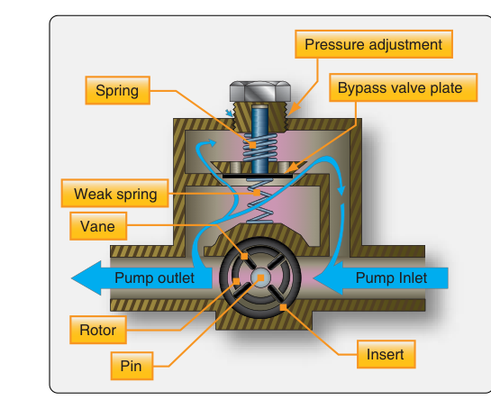
A pressure relief valve is a spring-loaded check valve installed in the fuel pump outlet circuit, usually integral to the pump body itself. The spring pre-load sets the cracking pressure — the precise outlet pressure at which the valve begins to open. When pump output pressure reaches this threshold, the valve lifts off its seat and routes excess fuel back to the pump inlet (bypass) or to the tank (return), reducing downstream pressure to the design value.
Cracking pressure is set by the spring's pre-load force acting against the valve's seating area, so a stronger spring or smaller seat area raises the pressure at which the valve opens, while a weaker spring or larger seat area lowers it. Spring rate and valve lift also influence how the valve behaves once it starts to open. Manufacturers pre-set this spring during production and publish the resulting pressure specification in the engine Type Certificate Data Sheet (TCDS) and the engine overhaul manual. Technicians must not substitute springs of different load ratings; doing so directly changes the regulated pressure.
At low engine speeds — idle, for example — the pump turns slowly and produces less volume. If the volume produced is just barely meeting demand, the relief valve stays closed because pressure never reaches cracking pressure. As engine speed increases and pump output rises above demand, the relief valve modulates open, maintaining a nearly constant pressure at the carburetor inlet or fuel control unit inlet.
Bypass vs. Return-to-Tank Configurations
In a bypass (recirculating) design, excess fuel is routed back to the inlet side of the pump. This is simple and common in Continental and Lycoming engines. One caution: recirculating fuel that has passed near hot engine components can absorb heat, raising fuel temperature and increasing the risk of vapor lock, especially on hot-soak restarts.
In a return-to-tank design, excess fuel flows back to the fuel tank. This prevents heat buildup in the recirculating loop and is more common in fuel-injected systems where precise fuel temperatures matter. However, it introduces a complication: fuel returning to the tank can agitate the fuel surface and, in some designs, may carry dissolved air back into the supply line if the return point is above the fuel level. Proper tank return-line placement addresses this in certified designs.
Pressure Regulation in Carbureted Systems
In a float-type carburetor system, the needle valve in the float bowl is the actual downstream pressure regulator. It opens and closes to maintain a near-constant fuel level in the float bowl, which sets the effective pressure head at the main discharge nozzle. The engine-driven pump relief valve simply ensures the pressure arriving at the carburetor inlet stays within the range the float needle can handle — typically 3 to 5 psi, depending on the specific engine and carburetor combination. Excessively high pump pressure forces the needle off its seat, flooding the bowl and causing an over-rich mixture, rough running, or engine stoppage due to liquid lock of the intake.
Pressure Regulation in Fuel-Injected Systems
Continental fuel injection systems use a fuel control unit (FCU) that receives pressurized fuel from the engine-driven pump and meters it to a flow divider, which then distributes precisely equal quantities to individual cylinder nozzles. Lycoming's design (licensed from Bendix/RSA) uses a servo regulator inside the fuel control unit that senses both fuel pressure and air throttle position to compute the correct fuel flow.
In these systems, there is typically a main relief valve at the pump and a secondary fuel control unit regulating valve inside the FCU. The pump relief valve holds a relatively high upstream pressure (often in the roughly 15–30 psi range depending on system type, engine-specific and verified against the applicable TCDS or overhaul manual); the FCU then reduces and meters this pressure to the nozzles at a much lower value — sometimes only a few psi above atmospheric at idle, rising to roughly 10–14 psi at full power depending on the system. This two-stage pressure management gives fine metering authority across the entire power range.
The Auxiliary (Electric) Boost Pump and Its Relief Valve
Most aircraft also have an electrically driven auxiliary pump used for engine start, takeoff, landing, and as a backup for pump failure. The auxiliary pump also has a relief valve, sized to match auxiliary pump output. Critically, the auxiliary pump relief valve must be set below the engine-driven pump relief pressure. This ensures that when the engine-driven pump is running normally, it simply overpowers the auxiliary pump without backpressure problems. If the auxiliary pump relief valve were set higher than the engine-driven pump, it could overpressurize the system whenever both pumps run simultaneously — a common test scenario.
Why It Matters: Safety and Airworthiness Consequences
A failed-open relief valve (stuck open, broken spring, contaminated seat) causes chronically low fuel pressure. The engine may run normally at high power where pump volume is high, but stumble or quit at low power and idle where pump volume is marginal. This symptom is often mistaken for a carburetor idle mixture problem.
A failed-closed or stuck-closed relief valve means there is no pressure limiting. Downstream pressure climbs until either a fitting leaks, a line ruptures, or the carburetor float needle is forced off its seat. A fuel leak in an engine compartment is a direct fire hazard. This is why correct relief valve operation must be verified per the manufacturer's overhaul manual and instructions for continued airworthiness whenever the engine is overhauled or a fuel system component affecting pressure regulation is replaced.
Vapor lock — fuel vaporizing in the lines before reaching the carburetor — is worsened by incorrectly high recirculating temperatures that result from a poorly designed or malfunctioning bypass loop. Maintaining correct relief valve pressure keeps fuel velocity high enough in the lines to suppress bubble formation.
Key Numbers and Rules
- Carbureted system inlet pressure: typically 3–5 psi; exact value specified in the engine TCDS and carburetor manual.
- Continental fuel injection pump pressure: typically in the roughly 15–30 psi range upstream of the FCU (model-dependent; verify against the specific TCDS/overhaul manual).
- Auxiliary (boost) pump relief pressure: always set lower than the engine-driven pump relief pressure to prevent over-pressurization when both run simultaneously.
- Spring pre-load is not field-adjustable on most certified designs; replacement with the correct part number is the approved corrective action.
- Relief valve cracking pressure is verified during engine test cell runs at overhaul per manufacturer overhaul manual and ICA procedures, with maintenance records documented per 14 CFR 43.9 and 43.11.
- Fuel pressure gauge indication in the cockpit reflects pressure downstream of the relief valve but upstream of the carburetor or FCU; a sudden drop or rise outside published limits is an airworthiness defect.
Common Test Traps
- Confusing bypass and return-to-tank: The FAA test may ask where excess fuel goes. In a bypass system it returns to the pump inlet; in a return system it returns to the tank. Know both configurations.
- Relief valve set pressure vs. cracking pressure: These terms are sometimes used interchangeably on tests, but technically the cracking pressure is when the valve first opens; full-flow relief pressure is slightly higher. Questions about the relief valve's purpose usually address cracking pressure.
- Auxiliary pump pressure lower, not higher: A classic distractor sets the auxiliary pump relief higher than the engine-driven pump. This is incorrect and dangerous; the auxiliary must always be the lower-pressure device.
- Low pressure at idle only: Students sometimes attribute this symptom to carburetor icing or mixture problems. A failed-open relief valve produces exactly this pattern — normal pressure at high power, subnormal pressure at idle — because the pump produces just enough volume at idle to meet demand, leaving the failed valve apparently inactive at high power.
- Regulating valve vs. relief valve: In fuel-injected systems, the FCU contains a regulating valve that actively meters fuel, not just limits maximum pressure. The relief valve protects against catastrophic over-pressure; the regulating valve controls normal operating pressure. The FAA test distinguishes these functions.