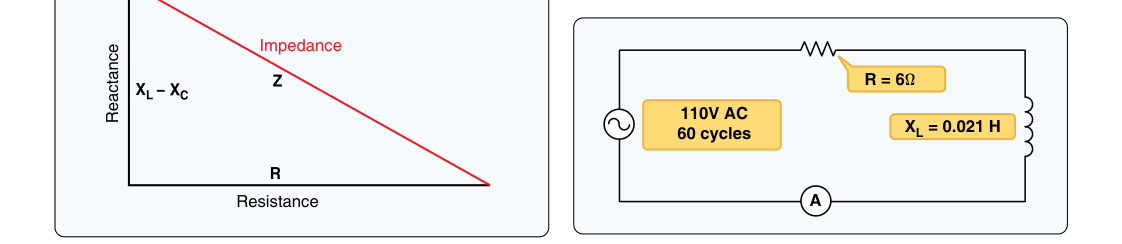
When electrons flow through a direct-current (DC) circuit, the only opposition they encounter is resistance — a property of the conductor material that converts electrical energy into heat. Alternating-current (AC) circuits are more complex. Because the voltage and current constantly reverse direction, two additional forms of opposition appear: capacitive reactance and inductive reactance. The combined effect of all three — resistance, capacitive reactance, and inductive reactance — is called impedance, symbolized by the letter Z and measured in ohms (Ω). Understanding impedance is essential for any aviation maintenance technician (AMT) working on aircraft electrical and avionics systems, where AC power at 400 Hz is the standard for most airborne equipment.
This article walks through each component of impedance in detail, explains how they combine, and covers the practical and exam-relevant points every AMT candidate needs to know.
Resistance in AC Circuits
Resistance (symbol R) behaves identically in both AC and DC circuits. It opposes current flow by converting electrical energy to heat, and it does so regardless of the direction or frequency of the applied voltage. In a purely resistive AC circuit, the voltage and current waveforms rise and fall together — they are said to be in phase. The phase angle between voltage and current is zero degrees. Ohm's Law applies directly: voltage equals current multiplied by resistance (V = IR), and resistive power is dissipated as true power, measured in watts.
Inductive Reactance
Any time current flows through a conductor it creates a surrounding magnetic field. In an AC circuit, the continually changing current means that magnetic field is also continually expanding and collapsing. This changing field induces a back-electromotive force (back-EMF) in the conductor itself that opposes the change in current — a phenomenon described by Lenz's Law. Coils and inductors are specifically designed to maximize this effect, but even a simple wire loop exhibits some inductance.
The opposition to current caused by this back-EMF is called inductive reactance, symbolized XL, and its formula is:
XL = 2πfL
where f is frequency in hertz and L is inductance in henries. Two key facts jump out of this formula. First, inductive reactance increases with frequency — at higher frequencies the current is changing faster, so the back-EMF is stronger and opposes current more. Second, inductive reactance increases with the size of the inductor. In aircraft AC systems operating at 400 Hz (rather than the 60 Hz household standard), inductive reactance is therefore roughly 6.7 times higher than it would be for the same component at 60 Hz. This is one reason aircraft AC components can be made physically smaller than their utility-power equivalents.
In a purely inductive circuit, current lags voltage by 90 degrees. Think of it this way: the inductor's back-EMF fights the rising current, so the current peaks one quarter-cycle behind the voltage. Because the current and voltage are 90° out of phase, no real (average) power is consumed by a pure inductor — the energy stored in the magnetic field during one half-cycle is returned to the circuit during the next. This type of power is called reactive power, measured in volt-amperes reactive (VAR).
Capacitive Reactance
A capacitor stores energy in an electric field between two conductive plates separated by an insulator (dielectric). In a DC circuit, once a capacitor is fully charged it blocks further current flow entirely. In an AC circuit, the constantly reversing voltage means the capacitor is continuously charging and discharging — so alternating current appears to flow through it, even though electrons never actually cross the dielectric gap.
The opposition a capacitor presents to this alternating current is called capacitive reactance, symbolized XC, and its formula is:
XC = 1 / (2πfC)
where f is frequency in hertz and C is capacitance in farads. Notice that capacitive reactance is inversely proportional to frequency — as frequency increases, capacitive reactance decreases. At very high frequencies, a capacitor looks almost like a short circuit; at very low frequencies or DC, it looks almost like an open circuit. This behavior is the opposite of inductive reactance and forms the basis for many filtering and tuning circuits used in aircraft radio and navigation equipment.
In a purely capacitive circuit, current leads voltage by 90 degrees. The capacitor must receive charge before a voltage can build across it, so the current flows first and the voltage follows. This is exactly opposite to the inductive situation. The mnemonic ELI the ICE man encodes this relationship: in an inductive (L) circuit, E (voltage) comes before I (current), meaning current lags; in a capacitive (C) circuit, I (current) comes before E (voltage), meaning current leads.
Combining Reactances: Impedance
In most real AC circuits, resistance, inductive reactance, and capacitive reactance are all present simultaneously. They cannot simply be added together algebraically because resistance and reactance are 90° out of phase with each other. Instead, they are combined using the impedance formula derived from the Pythagorean theorem:
Z = √[ R² + (XL − XC)²]
The term (XL − XC) is called the net reactance. If inductive reactance is larger, the net reactance is inductive and current lags voltage by some angle between 0° and 90°. If capacitive reactance is larger, the net reactance is capacitive and current leads voltage. If XL equals XC, they cancel exactly, the net reactance is zero, and the circuit behaves as if it were purely resistive — this condition is called resonance.
The phase angle (θ) between voltage and current can be found from: tan θ = (XL − XC) / R. A phase angle of 0° means purely resistive behavior; ±90° means purely reactive behavior.
Resonance and Its Practical Importance
At resonance, XL = XC, so net reactance equals zero and impedance equals resistance alone — its minimum possible value. In a series resonant circuit, this minimum impedance allows maximum current to flow at the resonant frequency. In a parallel resonant circuit, impedance is at its maximum at resonance, effectively blocking current at that frequency. Aircraft communication and navigation radios exploit resonance extensively to select a single desired frequency from the mix of signals present at the antenna.
Power in AC Circuits
Because voltage and current may be out of phase, not all of the apparent power delivered to an AC circuit performs useful work. Three power terms are important:
- True power (P) — the power actually consumed and converted to heat or mechanical work, measured in watts. P = I²R.
- Reactive power (Q) — power stored and returned by inductors and capacitors, measured in volt-amperes reactive (VAR).
- Apparent power (S) — the product of RMS voltage and RMS current without regard to phase angle, measured in volt-amperes (VA). S = V × I.
The ratio of true power to apparent power is the power factor (PF = P/S = cos θ). A power factor of 1.0 (unity) means all apparent power is doing useful work. A low power factor increases current demands on the generator and wiring without delivering proportionally more useful power — a concern when sizing aircraft electrical buses and generator capacity.
Key Numbers and Rules
- Aircraft AC systems typically operate at 400 Hz, which significantly increases inductive reactance and decreases capacitive reactance compared to 60 Hz utility power.
- Inductive reactance formula: XL = 2πfL — increases with frequency.
- Capacitive reactance formula: XC = 1/(2πfC) — decreases with frequency.
- Impedance formula: Z = √[R² + (XL − XC)²] — always in ohms.
- In a purely inductive circuit, current lags voltage by 90°.
- In a purely capacitive circuit, current leads voltage by 90°.
- At resonance, XL = XC, net reactance = 0, and Z = R (minimum impedance for a series circuit).
- Ohm's Law for AC circuits: I = V / Z, where Z replaces R.
Memory Aid
ELI the ICE man — a classic mnemonic for remembering phase relationships in AC circuits:
- ELI: In an inductive (L) circuit, E (EMF/voltage) comes before I (current) — current lags voltage.
- ICE: In a capacitive (C) circuit, I (current) comes before E (EMF/voltage) — current leads voltage.
Picture ELI the ICE man: a person whose name starts with the voltage-current relationship in inductors and ends with the relationship in capacitors. This single phrase consolidates two of the most frequently tested concepts in AC circuit theory.
Common Test Traps
- Adding reactances algebraically to resistance. Resistance and reactance are 90° out of phase, so they must be combined using the square-root-of-sum-of-squares formula, not simple addition. Forgetting this produces a wrong impedance value.
- Confusing which reactance increases with frequency. Inductive reactance goes UP as frequency increases; capacitive reactance goes DOWN. Test questions often swap these to catch the unprepared candidate.
- Thinking resonance eliminates all opposition. At series resonance, reactances cancel but resistance remains. Impedance equals resistance — it does not equal zero unless the circuit were a perfect (lossless) inductor and capacitor with no resistance.
- Applying DC Ohm's Law directly to AC circuits. In AC circuits, the denominator of Ohm's Law is impedance Z, not just resistance R. Using R alone ignores reactance and gives an incorrect (too-high) current value.
- Forgetting that 400 Hz changes component behavior. An inductor or capacitor behaves very differently at aircraft AC frequency (400 Hz) than at 60 Hz. AMT candidates must remember that higher frequency amplifies inductive reactance and reduces capacitive reactance — affecting component selection, sizing, and troubleshooting aboard aircraft.