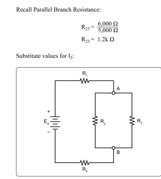
Modern aircraft are wired with hundreds of individual circuits, and virtually none of them are purely series or purely parallel in isolation. Most practical wiring arrangements are series-parallel circuits — combinations in which some components share a single current path (series) while others share the same voltage source across multiple independent paths (parallel). A thorough understanding of how to analyze these hybrid circuits is not just an academic exercise; it is a daily requirement for the Aviation Maintenance Technician (AMT) who must verify proper voltage drops, confirm current ratings, trace faults, and replace components without creating new hazards.
This article walks through the underlying theory, the step-by-step analysis method, the key numbers that appear on FAA knowledge tests, and the real-world traps that catch technicians off guard. Everything here is grounded in the FAA's Aviation Maintenance Technician Handbook — General (FAA-H-8083-30), which covers DC circuit theory in depth as part of the General knowledge area.
Review: Series vs. Parallel Fundamentals
Before tackling combined circuits, recall the defining characteristics of each type.
In a series circuit, all components are wired end-to-end along one continuous path. There is only one route for current to travel, so the same current flows through every element. Total resistance is the simple sum of all individual resistances (RT = R1 + R2 + R3 …). Voltage is divided among components in proportion to their individual resistances — a fact called the voltage divider principle. If any single component opens (fails), the entire circuit goes dead.
In a parallel circuit, all components connect across the same two nodes, sharing the same voltage. Current divides among the branches, with more current flowing through lower-resistance paths. Total resistance is always less than the smallest individual branch resistance. If one branch opens, the remaining branches continue to operate — the hallmark of aircraft bus design.
What Makes a Series-Parallel Circuit
A series-parallel circuit has at least one segment where components are in series with the rest of the circuit, and at least one segment where components are in parallel with each other. A simple but common aircraft example: a current-limiting resistor wired in series with a bus, feeding two landing lights wired in parallel across that bus. The resistor is in series with the combination; the lights are in parallel with each other. To analyze any property — total current, individual voltage drops, power dissipation — you must reduce the circuit systematically.
Step-by-Step Analysis Method
The standard technique taught in FAA handbooks is to simplify the circuit in stages, always working from the inside out — that is, from the most deeply nested combination back toward the source.
- Identify all series groups and parallel groups. Sketch or mentally label which components share a node pair (parallel) and which are chained end-to-end in the same path (series).
- Replace each parallel group with its equivalent resistance. For two resistors in parallel, use the product-over-sum formula: Req = (R1 × R2) / (R1 + R2). For three or more resistors in parallel, use the reciprocal formula: 1/RT = 1/R1 + 1/R2 + 1/R3 …, then take the reciprocal of the result.
- Add the series resistances together. Once parallel groups are replaced by single equivalent values, all remaining resistances are in series and can simply be summed to find total circuit resistance.
- Apply Ohm's Law to the total circuit. With total resistance and source voltage known, find total current: IT = E / RT.
- Work back through the circuit. Use total current and the equivalent resistances to find voltage across each section. Then use branch voltages and individual branch resistances to find individual branch currents. Verify by confirming that branch currents sum to the total current at each node (Kirchhoff's Current Law) and that voltage drops around any closed loop sum to the source voltage (Kirchhoff's Voltage Law).
Worked Example
Consider a 28-volt aircraft circuit (standard DC bus voltage) with the following layout: a 4-ohm resistor (R1) in series with a parallel combination of a 12-ohm resistor (R2) and a 6-ohm resistor (R3).
Step 1 — Parallel equivalent of R2 and R3: Req = (12 × 6) / (12 + 6) = 72 / 18 = 4 ohms.
Step 2 — Total resistance: RT = R1 + Req = 4 + 4 = 8 ohms.
Step 3 — Total current: IT = 28 / 8 = 3.5 amperes.
Step 4 — Voltage drop across R1: ER1 = IT × R1 = 3.5 × 4 = 14 volts.
Step 5 — Voltage across the parallel combination: Eparallel = 28 − 14 = 14 volts (also = IT × Req = 3.5 × 4 = 14 V — both methods agree).
Step 6 — Individual branch currents: IR2 = 14 / 12 ≈ 1.17 A; IR3 = 14 / 6 ≈ 2.33 A. Check: 1.17 + 2.33 = 3.5 A = IT. ✓
This step-by-step verification habit is essential when working on real aircraft; it catches calculation errors before they lead to an improperly sized wire or a tripped circuit breaker in service.
Kirchhoff's Laws in Practice
Kirchhoff's Current Law (KCL) states that the total current entering any node equals the total current leaving that node — current cannot accumulate. In a series-parallel circuit, this means that at every junction where the circuit branches, the sum of branch currents equals the current arriving from the series portion. Technicians use KCL when isolating a single high-resistance branch that is pulling less than its share of current — a classic sign of a developing open fault.
Kirchhoff's Voltage Law (KVL) states that the sum of all voltage drops around any closed loop equals the source electromotive force (EMF). In a series-parallel circuit you can trace any closed path — including paths through parallel branches — and the drops must balance the supply. If a voltmeter reading does not match the calculated drop, excess resistance somewhere (corroded connector, failing component) is absorbing voltage it should not.
Why This Matters for Aircraft Systems
Aircraft electrical systems are designed around predictable current and voltage behavior. When an AMT installs a replacement component with a different resistance than the original, the entire series-parallel balance shifts. A higher-resistance replacement in a parallel branch draws less current and may run cooler — or may not provide enough magnetic force if it is a relay coil. A lower-resistance replacement draws more current, which flows back through the series portion of the circuit, potentially overheating wiring or nuisance-tripping a circuit breaker.
Avionics buses, lighting circuits, and motor control circuits all rely on parallel branching protected by series elements (fuses, circuit breakers, or resistors). Understanding the combined behavior allows technicians to verify that a repaired circuit will not exceed the ampacity of the wiring or the rating of the overcurrent protection device — both of which are airworthiness requirements under 14 CFR Part 43 and the aircraft's type design data.
Key Numbers and Rules
- 28 V DC is the standard bus voltage for most transport-category and many general aviation aircraft; 14 V DC is common in smaller single-engine aircraft. Always confirm source voltage before calculating expected drops.
- Parallel equivalent resistance is always less than the smallest individual branch resistance. If your calculated RT is larger than any one branch, recheck your arithmetic.
- Series voltage drops are additive — they must sum exactly to the source voltage. A measured total that differs by more than a few millivolts indicates a hidden resistance (bad connection, corroded terminal).
- Power in each component: P = I² × R, or P = E² / R, or P = I × E. All three forms of the power equation come from Ohm's Law. On the FAA General test, you may be asked to calculate watts dissipated in a specific branch.
- Reciprocal formula for parallel resistance: 1/RT = 1/R1 + 1/R2 + … (take the reciprocal of the sum to get RT). A common error is forgetting the final reciprocal step.
- Equal resistors in parallel: Two equal resistors R in parallel yield R/2. Three equal resistors in parallel yield R/3. This shortcut saves time on timed knowledge tests.
Common Test Traps
- Forgetting the final reciprocal. When using the reciprocal formula for parallel resistance, many students compute 1/RT correctly but report that value as RT. Always flip the result one more time.
- Applying series current rules to parallel branches. In a parallel group, each branch has a different current if the resistances differ. Only the series portion of a series-parallel circuit carries a single uniform current value.
- Assuming total voltage drops across the parallel group. In a series-parallel circuit, the source voltage is shared between the series element(s) and the parallel group. The full source voltage does not appear across the parallel combination unless the series resistance is zero.
- Ignoring internal resistance of the source. FAA test problems sometimes include source (battery) internal resistance as a series element. Treat it exactly like any other series resistor when calculating total circuit resistance and total current.
- Mixing up power formulas for series vs. parallel sections. When asked for total power, use total current and total resistance (P = IT² × RT). When asked for power in an individual parallel branch, use that branch's own current and resistance — not the total current.
Mastering series-parallel circuit analysis gives the aviation maintenance technician a powerful diagnostic framework. Whether you are bench-testing a replacement avionics tray, tracing an intermittent fault in a landing-gear indication circuit, or verifying that a modified lighting installation stays within wiring ampacity limits, the same systematic approach applies: identify the topology, reduce parallel groups to equivalents, sum the series elements, apply Ohm's Law, and verify with Kirchhoff's Laws. Practice the worked-example method until it is second nature, and you will find both the FAA General knowledge test and real-world troubleshooting significantly more manageable.