Electricity powers nearly every system on a modern aircraft, from ignition and lighting to avionics and flight controls. Before an aviation maintenance technician (AMT) can safely diagnose a faulty circuit or install new wiring, they must have a firm grasp of the fundamental law that governs all electrical behavior: Ohm's Law. Named after German physicist Georg Simon Ohm, this principle describes the precise, predictable relationship between three key quantities — voltage, current, and resistance. Understanding it is not merely an academic exercise; it is the everyday tool an AMT reaches for when a circuit breaker keeps tripping, a motor runs sluggishly, or a lamp fails to illuminate.
This article covers Ohm's Law from first principles, shows how it applies in series, parallel, and series-parallel aircraft circuits, and highlights the practical troubleshooting implications that appear both on the FAA General Knowledge Test and in the hangar.
The Three Fundamental Quantities
To apply Ohm's Law correctly, you first need a clear mental picture of the three quantities it relates.
- Voltage (E or V) — Electrical pressure, measured in volts (V). Voltage is the force that pushes electrons through a conductor. Aircraft use 14-volt or 28-volt DC systems (derived from 12-V or 24-V batteries plus a generator or alternator), and some large transport aircraft use 115-volt, 400-Hz AC systems. Voltage is always measured between two points — it is a difference in electrical potential.
- Current (I) — The rate of electron flow, measured in amperes (A). One ampere equals one coulomb of charge passing a point per second. Current is what actually does the work in a circuit — spinning a motor, heating a pitot tube, or energizing an electromagnet. Current flows through a circuit and is the same value everywhere in a simple series loop.
- Resistance (R) — The opposition to current flow, measured in ohms (Ω). Every conductor, every component, and even the aircraft structure (when used as a ground return) presents some resistance. Resistance converts electrical energy into heat, which is useful in heating elements but wasteful — and potentially dangerous — in wiring that should simply carry current efficiently.
Ohm's Law: The Core Formula
Ohm's Law states that the current flowing through a conductor is directly proportional to the voltage applied across it and inversely proportional to its resistance. Expressed as a formula:
E = I × R
Where E is voltage in volts, I is current in amperes, and R is resistance in ohms. From this single equation, two rearrangements are equally important:
- I = E ÷ R — Use this to find current when you know voltage and resistance.
- R = E ÷ I — Use this to find resistance when you know voltage and current.
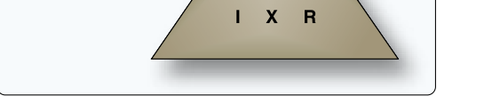
A handy memory device is the Ohm's Law triangle: write E at the top, I at the lower left, and R at the lower right. Cover the quantity you want to find, and the remaining two show the operation — covering I reveals E over R (divide); covering R reveals E over I (divide); covering E reveals I next to R (multiply).
Worked Examples in Aircraft Circuits
Concrete numbers make Ohm's Law stick. Consider these aircraft-relevant scenarios.
Example 1 — Finding current draw: A landing light on a 28-volt system has a resistance of 3.5 Ω. How much current does it draw? Using I = E ÷ R: I = 28 ÷ 3.5 = 8 amperes. Knowing this tells the technician what gauge wire and what circuit breaker rating are appropriate.
Example 2 — Finding unknown resistance: An ammeter reads 4 A in a 24-volt circuit. What is the load resistance? R = E ÷ I = 24 ÷ 4 = 6 Ω. If the component's specification calls for 8 Ω, the lower-than-expected resistance suggests a partial short circuit that warrants further investigation.
Example 3 — Voltage drop in a wire: A wire feeding a motor has 0.4 Ω of resistance and carries 10 A. The voltage drop across the wire is E = I × R = 10 × 0.4 = 4 volts. On a 28-volt system, that 4-volt drop means the motor only sees 24 volts — potentially enough to cause sluggish operation and overheating. This demonstrates why wire sizing and connection quality matter enormously in aircraft work.
Ohm's Law in Series Circuits
In a series circuit, components are connected end-to-end so that the same current flows through every element. Total resistance is simply the sum of all individual resistances: RT = R1 + R2 + R3 … The supply voltage divides proportionally across each resistor according to Ohm's Law — a phenomenon called a voltage divider. If any component in a series circuit opens (fails to infinite resistance), current stops flowing entirely and all loads in the circuit go dead. This explains why older aircraft interior lighting strings using series wiring caused complete circuit outages when a single bulb burned out.
Ohm's Law in Parallel Circuits
In a parallel circuit, each load is connected directly across the supply voltage, so every branch sees the same voltage. Current divides among the branches inversely proportional to each branch's resistance — a branch with lower resistance draws more current. Total resistance in a parallel circuit is always less than the smallest individual branch resistance, calculated by: 1 ÷ RT = 1 ÷ R1 + 1 ÷ R2 + … Most aircraft electrical loads are wired in parallel, ensuring that if one device fails, others continue operating normally. Adding more loads in parallel decreases total circuit resistance and increases total current drawn from the source — critical knowledge when assessing alternator or generator load limits.
Series-Parallel Circuits
Real aircraft circuits are often series-parallel combinations: a single feed wire (with its resistance) in series with several parallel loads. To analyze these, the AMT first combines the parallel branches into a single equivalent resistance using the parallel formula, then adds that result in series with any remaining series resistances. Ohm's Law then yields total current, from which individual branch currents and voltage drops can be calculated step by step.
Why It Matters for Aircraft Maintenance
Ohm's Law is not just textbook theory — it underpins every electrical troubleshooting task an AMT performs. High resistance caused by corroded terminals, loose connections, or undersized wire creates excess voltage drop that starves components of the power they need and generates heat that can damage insulation or start fires. Low resistance caused by chafed wire insulation creating a short to ground causes excessive current that trips circuit breakers or, in an unprotected circuit, melts wire and can ignite surrounding materials.
When an AMT measures voltage, current, or resistance with a multimeter, they are gathering the raw data that Ohm's Law transforms into actionable conclusions. A circuit that reads 28 V at the bus but only 22 V at the load immediately points to a 6-volt drop somewhere in the supply path — Ohm's Law and the measured current pinpoint which segment of wiring or which connector is at fault.
Key Numbers and Rules
- Standard light aircraft DC bus voltages: 14 V (12-V battery system) or 28 V (24-V battery system).
- Ohm's Law triangle: E = I × R, rearranged to I = E ÷ R and R = E ÷ I.
- In a series circuit, total resistance increases with each added component; a single open kills all current.
- In a parallel circuit, total resistance decreases with each added branch; an open in one branch does not stop current in others.
- Voltage drop in a wire = current × wire resistance. Excessive drop indicates high resistance in the path.
- Power (watts) is related by P = E × I, which combines with Ohm's Law to yield P = I² × R and P = E² ÷ R — the Watt's Law extensions.
- Circuit breaker ratings are selected to protect the wire, not the load, based on the wire's maximum current-carrying capacity.
Memory Aid
The classic Ohm's Law triangle (also called the EIR triangle) is the standard mnemonic recognized throughout AMT training materials. Draw a triangle, place E at the top, I at bottom-left, and R at bottom-right. To solve for any variable, cover it with your finger: covering E shows I × R (multiply); covering I shows E ÷ R (divide); covering R shows E ÷ I (divide). The triangle makes unit relationships immediately visual and eliminates algebraic errors during fast troubleshooting.
Common Test Traps
- Confusing voltage drop with voltage: The FAA exam may describe a circuit where the bus voltage and the voltage at the load differ, then ask you to find resistance or current. Remember to use the voltage across the component in Ohm's Law, not the supply voltage, if a wire drop has already been stated.
- Parallel resistance always decreasing: Students sometimes add resistances in parallel the same way they do in series. The reciprocal formula always yields a total resistance less than the smallest branch — if your answer is larger, you made an arithmetic error.
- Units mismatch: Resistance given in kilohms (kΩ) must be converted to ohms before plugging into formulas. A 2.2 kΩ resistor = 2,200 Ω. Forgetting the conversion leads to answers off by a factor of 1,000.
- Ohm's Law applies to linear (resistive) components only: It does not directly apply to non-linear devices like diodes or transistors in the way simple E = IR implies. The exam tests understanding of where the law is valid.
- Open versus short circuit confusion: An open circuit has infinite resistance, so current = 0. A short circuit has zero (or near-zero) resistance, so current becomes very large. Students sometimes mix these up when predicting whether a circuit breaker trips (short = excessive current = trip; open = no current = no trip).