Modern aircraft electrical systems rarely run on a single voltage type. Most transport-category and many general aviation aircraft depend on both direct current (DC) and alternating current (AC) to operate the full suite of cockpit instruments, avionics, motors, and lighting. Two key conversion devices bridge the gap between these worlds: the inverter, which turns DC into AC, and the transformer-rectifier unit (TRU), which turns AC into DC. Understanding how each device works, where it fits in the power architecture, and how to inspect or troubleshoot it is essential knowledge for any airframe technician — and a frequent topic on the FAA AMT Airframe knowledge test.
This article walks through the operating principles, construction, system roles, maintenance considerations, and common failure modes of both inverters and TRUs, grounded in the FAA Aviation Maintenance Handbook — Airframe (FAA-H-8083-31) and the General handbook (FAA-H-8083-30).
Why Aircraft Need Both AC and DC
Older piston-powered general aviation aircraft traditionally ran almost exclusively on 14-volt or 28-volt DC systems powered by an engine-driven alternator (or generator) and a battery. DC works well for starter motors, lighting, and simple avionics. However, certain loads demand AC: gyroscopic flight instruments driven by AC induction motors, fluorescent lighting systems, and many modern avionics boxes that internally regulate their own AC supply. Many transport-category jets and turboprops generate 115-volt, 400-Hz AC as a primary bus, then derive 28-volt DC from it through TRUs for other loads — though this is one common architecture, not a universal one; some modern aircraft use variable-frequency AC systems or DC-centered architectures instead. Smaller aircraft may flip this: generate DC as the primary source and use inverters to produce the AC needed by specific instruments.
The 400 Hz frequency (versus the 60 Hz household standard) is not accidental. Higher frequency allows transformers and motors to be physically smaller and lighter for the same power output — a crucial advantage in aviation where every pound counts. An AC motor designed for 400 Hz can be made significantly smaller and lighter than an equivalent 60 Hz motor, roughly in proportion to the frequency ratio, though the precise size reduction depends on the specific design rather than a single fixed figure.
Inverters: Converting DC to AC
An inverter accepts DC voltage from the aircraft bus or battery and outputs regulated AC voltage at the required frequency, typically 115 volts AC at 400 Hz, or sometimes 26 volts AC at 400 Hz for specific instrument buses.
Static Inverters
Modern aircraft use static inverters, which contain no rotating parts. Inside a static inverter, solid-state switching transistors or similar semiconductor devices chop the DC input on and off at a controlled rate, producing a square or modified sine wave at the desired frequency. Filtering and regulation circuitry then smooth the output toward a clean sine wave at stable voltage and frequency. Static inverters are highly reliable because the absence of moving parts eliminates the bearing wear and brush arcing associated with older rotating designs. They are also quiet, compact, and efficient.
Rotary Inverters (Historical Context)
Older aircraft used rotary inverters — essentially a DC motor mechanically coupled to an AC generator on a common shaft. The DC motor turns the shaft, and the AC generator portion produces the desired AC output. While effective, rotary inverters suffer from higher maintenance demands: brushes wear, bearings need lubrication, and the rotating mass can introduce vibration. Most modern designs have replaced rotary units with static inverters, but airframe technicians working on legacy aircraft will still encounter them. The FAA-H-8083-31 covers both types.
Inverter Regulation and Monitoring
Both voltage and frequency must be tightly regulated. Gyroscopic instruments, for example, are sensitive to frequency variation — a gyro spinning at the wrong speed due to off-frequency AC power will produce erroneous attitude or heading indications. Aircraft systems therefore include sensing circuits that monitor inverter output; if voltage or frequency drifts outside limits, cockpit warning lights or annunciators alert the crew. Technicians testing inverter output must use equipment capable of measuring both RMS voltage and frequency accurately — a standard multimeter set to AC volts alone is insufficient for a complete inverter serviceability check.
Transformer-Rectifier Units (TRUs): Converting AC to DC
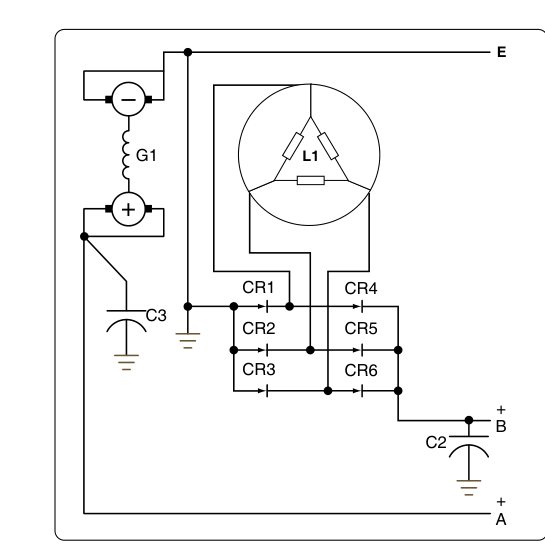
A transformer-rectifier unit performs the opposite conversion: it takes AC from the aircraft's AC bus and delivers regulated DC, typically 28 volts DC, to DC buses that power avionics, battery charging circuits, and other DC loads.
Internal Construction
A TRU contains two main functional stages working in sequence:
- Transformer stage: Steps the incoming AC voltage up or down to the required level before rectification. In a typical transport aircraft, the 115-volt AC bus is stepped down inside the TRU prior to rectification.
- Rectifier stage: A network of diodes — arranged in a full-wave bridge or a three-phase bridge configuration — converts the AC sine wave into pulsating DC. In three-phase aircraft systems, a six-diode (or twelve-diode for higher-quality output) bridge rectifier dramatically reduces output ripple, producing a very smooth DC output without the need for large filter capacitors.
The result is a solid-state, no-moving-parts unit that is highly reliable, produces little noise, and requires minimal routine maintenance beyond periodic inspection. Because diodes are the primary active components, most TRU failures manifest as diode opens or shorts, which either reduce output voltage or cause AC ripple to appear on the DC bus — both detectable with appropriate test equipment.
TRUs in the System Architecture
On large transport aircraft, TRUs are the primary source of 28-volt DC. They are sized to handle the full DC load without assistance from the battery during normal operations; the battery is reserved for emergency use and engine starting. Multiple TRUs may be installed for redundancy, each feeding a separate DC bus. If one TRU fails, bus tie logic can connect the remaining TRU(s) to sustain essential DC loads. The FAA-H-8083-31 emphasizes that technicians must understand load calculations to ensure a replacement TRU is rated for the bus it serves — undersized TRUs overheat and fail prematurely.
Key Numbers and Rules
- Primary AC bus voltage and frequency (transport aircraft): 115 volts AC, 400 Hz, three-phase.
- Instrument AC bus (some GA aircraft): 26 volts AC, 400 Hz, single-phase — fed by a dedicated inverter.
- Standard DC bus voltage: 28 volts DC (nominal) in most transport and high-performance aircraft; 14 volts DC in smaller GA aircraft.
- 400 Hz advantage: Transformer and motor weight is dramatically reduced compared to 60 Hz designs — a direct weight-savings benefit.
- TRU output ripple: Acceptable ripple is typically specified in the aircraft's maintenance manual; excessive ripple indicates diode failure or open filter components.
- Static inverter advantage: No brushes, no bearings — maintenance interval requirements are far longer than for rotary inverters.
- Inverter output checks: Must verify both voltage (RMS) AND frequency — gyro instruments are sensitive to both parameters.
Inspection and Troubleshooting
Routine airframe maintenance of inverters and TRUs focuses on security of mounting, condition of electrical connectors, absence of overheating evidence (discoloration, burnt odor, melted insulation), and verification of output parameters per the Aircraft Maintenance Manual (AMM). Because both units are primarily solid-state, they are often treated as line-replaceable units (LRUs) — meaning the defective unit is removed and sent to a certified repair station, and a tested serviceable unit is installed in its place.
When troubleshooting an inverter, the technician should first confirm that DC input voltage is correct and within limits before condemning the inverter itself. A low or noisy DC input (from a failing alternator or corroded connection) can cause an otherwise good inverter to produce out-of-tolerance AC output. Similarly, when troubleshooting a TRU, confirming that the AC input is present, correctly phased (for three-phase systems), and within voltage limits eliminates upstream causes before the TRU is replaced.
Overheating is the leading life-limiter for both devices. Many installations include thermal switches that disconnect the unit if internal temperature exceeds limits. Adequate airflow to cooling fins or fans must be maintained, and technicians should never block ventilation paths when reinstalling units or adding nearby equipment.
Why It Matters for Safety and Airworthiness
Instrument failures caused by inverter malfunctions have contributed to spatial disorientation incidents. If the AC-powered attitude gyro or directional gyro loses power in IMC and the pilot is unaware, the result can be catastrophic. This is why most IFR-equipped aircraft include redundant inverters (a main and a standby) and why cockpit annunciation of inverter failure is required. Airframe technicians who properly test and certify inverter output — not just verify that a light comes on — directly contribute to flight safety.
TRU failures, while less immediately dramatic, can silently degrade avionics performance through ripple contamination of the DC bus, cause erratic autopilot behavior, or trigger nuisance circuit-breaker trips. Recognizing these symptoms and tracing them to a TRU is a core competency for any airframe technician working on modern aircraft.
Common Test Traps
- Rotary vs. static inverter confusion: The FAA knowledge test may ask which type has no moving parts — that is the static inverter. Rotary inverters use a DC motor driving an AC generator.
- Frequency matters as much as voltage: Many students remember to check output voltage but forget that inverter frequency must also be verified; gyro instruments depend on both.
- TRU and battery charging: A TRU converts AC to regulated DC, and on many transport aircraft that regulated DC output is used directly to charge and maintain the battery as part of the normal system design — not only through a separate, independent charging circuit. Assuming a TRU has no role in battery charging is a common error.
- 400 Hz vs. 60 Hz: Questions about why aircraft use 400 Hz rather than 60 Hz target the weight-savings rationale — smaller, lighter transformers and motors — not any safety or regulatory requirement.
- Three-phase rectification: TRUs on transport aircraft use three-phase AC input and multi-diode bridge rectifiers for smooth DC output. Assuming a TRU is a simple single-phase device leads to wrong answers about ripple characteristics and diode count.