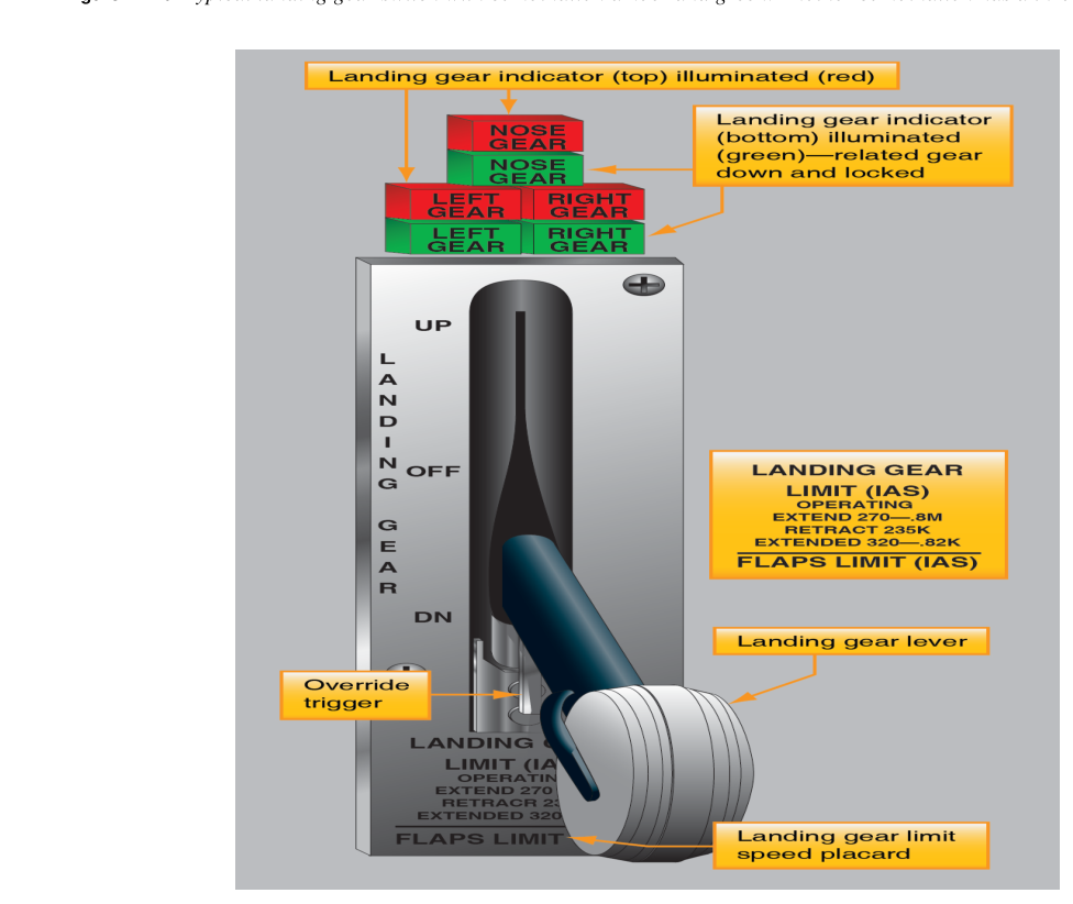
Every time an aircraft touches down, the landing gear must be fully extended and locked into position. While a pilot can sometimes verify main gear position visually, the nose gear and the locking status of all gear legs are invisible from the cockpit. That is why retractable-gear aircraft certificated under 14 CFR Part 23 or Part 25 are required by the applicable landing gear design standards (14 CFR 23.729 and 25.729) to carry a gear position indicating system: a combination of sensors, wiring, cockpit lights, and audible warnings that continuously report whether each gear is up and locked, down and locked, or somewhere in between. For the aviation maintenance technician working on airframe systems, understanding how these systems are designed, how they fail, and how they are inspected is not just a test requirement—it is a direct safety responsibility.
This article covers the complete system: the sensors that detect gear position, the cockpit light logic, the aural warning horn and its triggering conditions, the squat switch, and the maintenance considerations that keep everything reliable. Values and design principles referenced here are grounded in the FAA Aviation Maintenance Handbook—Airframe (FAA-H-8083-31) and the Pilot's Handbook of Aeronautical Knowledge (FAA-H-8083-25).
How the Position Indicating System Works
The core job of a gear indicating system is to answer three questions simultaneously for each gear leg: Is it up and locked? Is it down and locked? Is it still moving? Answering those questions requires position sensors at every gear leg, a circuit that interprets sensor signals, and cockpit indicators that display the result in a format a pilot can scan in a fraction of a second.
Position Sensors — Microswitches and Proximity Sensors
The most common position sensor is the microswitch, also called a limit switch. A small actuating arm contacts a cam or tang that moves with the gear or the uplatch/downlatch mechanism. When the gear reaches the fully-up-and-locked position, the uplatch cam depresses the switch; when fully down and locked, the downlatch cam depresses its switch. The switch changes the state of an electrical circuit, which drives the cockpit indicator.
Many modern aircraft use proximity sensors (also called proximitry switches or Hall-effect sensors) instead of mechanical microswitches. A proximity sensor has no moving parts: a small electromagnetic field is generated by the sensor, and when a metallic target attached to the gear or latch mechanism enters the field, the sensor produces an output signal. Because there is no physical contact, proximity sensors are more resistant to wear, vibration, and contamination. The output is still an electrical signal that feeds the same cockpit indicator logic.
Cockpit Light Logic — Green, Red, and Dark
The universally adopted color convention is straightforward:
- Green light (one per gear leg): The gear is down and locked. Three green lights means all three legs are fully extended and their downlatch mechanisms have engaged. This is the required condition for landing.
- Red light (often a single warning light): The gear is in an unsafe or in-transit condition. The red light illuminates any time one or more gear legs is not in the commanded position—for example, gear selected up but not yet fully retracted, or gear selected down but a downlock has not engaged.
- No light (dark): On most designs, a dark panel with gear selected up indicates the gear is up and locked. Gear-up lights are less common because the up-and-locked condition is the normal cruise configuration; using darkness to signal it conserves indicator space and avoids pilot confusion from a continuously illuminated light.
Some aircraft do use separate up-and-locked lights, and a few use a single multi-color indicator per leg. Regardless of the specific design, the technician must verify that the system installed matches what is described in the aircraft's FAA-approved Aircraft Flight Manual (AFM) and maintenance manual.
In-Transit Indication
During gear travel—neither fully up nor fully down—the red warning light (or lights) illuminates. On aircraft with electronic gear position indicators, an animated icon may show gear legs in motion. The red in-transit condition is normal and expected during a gear cycle, but if the red light remains illuminated after the gear cycle should be complete (typically 5 to 10 seconds depending on aircraft type), the crew must treat it as a malfunction and consult the abnormal procedures checklist.
The Aural Warning Horn
Visual lights alone are not enough if a pilot's attention is directed outside the cockpit during an approach. The gear warning horn provides an aural alert whenever the aircraft is configured for landing but the gear is not down and locked. The horn circuit is typically triggered by any combination of the following conditions:
- Throttle position: On piston aircraft, the horn activates when the throttle is retarded below a certain power setting (often idle or near-idle) and the gear is not down and locked. This mimics the approach-to-landing power reduction.
- Flap position: On aircraft with flap-activated switches, extending flaps beyond a set threshold (such as beyond the approach flap setting) with gear retracted triggers the horn.
- Airspeed: Some aircraft use an airspeed switch or a combination of airspeed and configuration sensors. Below a defined airspeed with gear not down, the horn sounds.
Most aircraft use at least two of these triggers in combination to reduce nuisance warnings. For example, the horn may require both low throttle AND flaps extended before it activates. The technician must verify that all trigger paths are functional independently during system checks—a failed throttle switch could silence the horn even if the flap switch is serviceable.
The Squat Switch (Weight-on-Wheels Switch)
The squat switch, formally called the weight-on-wheels (WOW) switch or ground safety switch, is a critical component that prevents inadvertent gear retraction while the aircraft is on the ground. It is usually a microswitch mounted on the main gear strut or actuating linkage. When the strut compresses under the weight of the aircraft, the squat switch opens (or closes, depending on design) a circuit that disables the gear retraction command. If a pilot accidentally selects gear up on the ground, the squat switch prevents the actuator from retracting the gear.
The squat switch also plays a role in the warning horn logic on many aircraft: the horn circuit is bypassed when the squat switch signals weight-on-wheels, so the horn does not blare during taxi. Technicians must confirm correct squat switch adjustment during maintenance. A switch rigged too loosely may not signal weight-on-wheels at all rotations speeds; a switch rigged too tightly may prevent gear retraction immediately after takeoff when the strut is still slightly compressed.
Why These Systems Matter
Gear-up landings are among the most common and most preventable serious aircraft accidents. Even when a pilot knows the gear is down visually, a downlock failure means the gear can collapse on touchdown. The position indicating system is the last line of defense, confirming not just that the gear is extended but that the locking mechanism has positively engaged. From a maintenance standpoint, a failed position indicator is not simply an annunciator problem—it degrades the safety chain that protects against a catastrophic gear collapse.
The warning horn is equally critical. Multiple accident investigations have identified cases where warning horn circuits were silenced by maintenance errors, pulled circuit breakers, or failed switches. Regulations under 14 CFR Part 91 require that required instruments and equipment be operative for flight; a non-functional gear warning horn renders the aircraft not airworthy for flight under the required equipment list.
Key Numbers and Rules
- Three green, safe to land: All three gear legs down and locked. This is the universally taught and tested indicator configuration.
- Red light in transit: Normal during gear cycling; abnormal if it persists beyond the expected cycle time.
- Dark (no light) gear-up configuration: Normal in cruise on most aircraft with this design—but the technician must know the specific aircraft's design before assuming.
- Squat switch function: Disables retraction command on ground; must be correctly adjusted per the aircraft maintenance manual (AMM) rigging specifications.
- Horn circuit checks: Each trigger path (throttle, flap, airspeed switch) must be checked independently during maintenance to ensure full-system horn function.
- Bulb/LED checks: FAA-H-8083-31 emphasizes that gear indicator lights must be checked for proper operation during preflight and after maintenance; burned-out indicator bulbs are a common and insidious failure mode.
Common Test Traps
- Dark panel does NOT mean malfunction: Students often flag a dark gear indicator as a warning. On most aircraft a dark panel with gear handle UP simply means the gear is up and locked—the normal cruise state. Only a red light or a green light when gear is commanded up would signal a problem.
- Green light confirms downlock, not just extension: The green light is wired to the downlock sensor, not to a simple proximity of the gear leg. A gear that is extended but has not fully engaged its downlatch will not show green. This distinction is critical for understanding what the system is actually confirming.
- Squat switch prevents retraction but does not prevent extension: The squat switch only inhibits the retract command. The extend command can still be issued on the ground, which is how ground functional tests are performed with proper safety procedures.
- Horn circuit breaker abuse: A pulled gear warning horn circuit breaker is a serious airworthiness concern. Some pilots pull it to silence nuisance warnings; this is not an approved action and leaves the aircraft without its required warning system.
- Proximity sensor vs. microswitch failure modes differ: A failed microswitch often causes an open circuit (no signal), while proximity sensors can fail in ways that produce a continuous signal. Understanding which sensor type is installed tells the technician which failure mode to expect during troubleshooting.
A thorough understanding of landing gear position indicating systems—from the sensor at the gear leg to the light in the cockpit to the horn that warns of an unsafe approach—is fundamental to safe airframe maintenance. Every component in this safety chain must be verified as correctly installed, adjusted, and functional before any retractable-gear aircraft is returned to service.