Many light general aviation aircraft rely on a vacuum system to power their gyroscopic flight instruments — specifically the attitude indicator (AI) and the heading indicator (HI). These instruments depend on a rapidly spinning gyroscope rotor, and in a vacuum-driven system, that spin is generated by a stream of air drawn across buckets or vanes cut into the rotor. The vacuum system pump creates the suction that moves this air, while the relief valve ensures the suction level stays within the precise range the instruments need. Understanding how these components are built, how they work, and how they fail is essential knowledge for any airframe and powerplant technician — and it is heavily tested on the FAA AMT Airframe knowledge exam.
This article covers the types of vacuum pumps used in certificated aircraft, how each type generates suction, the role and adjustment of the relief valve, the system's overall layout, and the maintenance and inspection considerations that keep these systems airworthy.
How the Vacuum System Works
At its core, a dry-air vacuum system is a closed-loop suction circuit. The pump — driven by the engine accessory section — pulls air out of the instrument cases. As air is drawn out, fresh filtered air enters the instrument case through an inlet filter, flows across the gyro rotor, and spins it. A relief valve, plumbed in the suction line between the instruments and the pump inlet, bleeds in ambient air whenever suction rises above the desired level, acting as a pressure regulator in the suction sense. A cockpit-mounted suction gauge lets the pilot or technician confirm that system vacuum is within the green arc, typically between about 4.5 and 5.5 inches of mercury (in. Hg) for most light aircraft gyroscopic instruments, though manufacturers specify the exact range for each installation.
Types of Vacuum Pumps
Wet-Type (Oil-Lubricated) Pumps
Older aircraft designs frequently used wet-type vacuum pumps, also called oil-lubricated pumps. These pumps are gear-driven from the engine and use engine oil for internal lubrication. Because oil mist passes through the pump and into the discharge air, a wet-type system requires an oil separator installed on the discharge (outlet) side of the pump to remove oil from the air before it is vented overboard, preventing oil contamination and mess. The separator collects oil droplets and returns them to the engine sump via a drain line. Wet systems also need an air-oil separator filter that must be serviced regularly. The primary advantage of these pumps is long service life; the primary disadvantage is the additional plumbing, weight, and maintenance burden of the oil separation components.
Dry-Type (Self-Lubricating) Pumps
The vast majority of modern light aircraft use dry-type, vane-type vacuum pumps. These pumps contain a slotted rotor mounted eccentrically inside a cylindrical housing. Carbon vanes fit loosely in the rotor slots and are thrown outward by centrifugal force against the housing wall as the rotor spins. The geometry of the eccentric housing causes the volume between adjacent vanes to change as the rotor turns, compressing air on one side and creating suction on the other. Because the vanes are made of a self-lubricating carbon composite material, no external lubrication is required and no oil separator is needed. This simplifies the system considerably.
The tradeoff is vane wear. Carbon vanes slowly erode against the housing, and the pump has a finite service life measured in hours. A worn pump may no longer generate adequate suction, and a sudden catastrophic vane failure can leave the gyroscopes without power — a serious hazard during instrument meteorological conditions (IMC). Because of this, many maintenance programs recommend replacing dry-type pumps on a calendar- or hours-based schedule rather than waiting for failure. Manufacturers publish time between overhaul (TBO) or replacement intervals that technicians must follow per the aircraft maintenance manual.
Dry-type pumps can be further subdivided by their port configuration. Most are single-acting pumps, meaning suction is generated on one port and the exhaust (higher-pressure discharge) exits on the other. Some aircraft use the pump's discharge side to power pneumatic de-ice boots, taking advantage of the positive pressure available at the outlet.
Venturi Tubes
Some older or simpler aircraft use a venturi tube mounted on the airframe exterior rather than an engine-driven pump. Ram airflow through the venturi creates suction. While simple and reliable in a mechanical sense, venturis only develop adequate suction above certain airspeed thresholds and are entirely useless on the ground, making them unsuitable for modern IFR operations. They are largely of historical interest but may appear on knowledge exams.
The Relief Valve
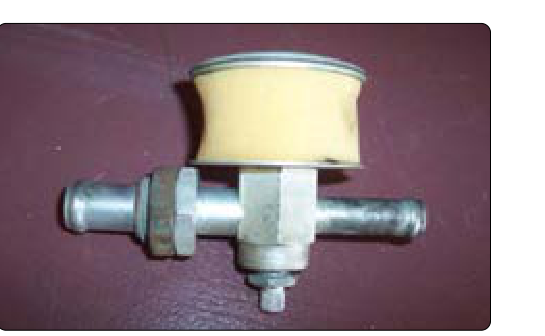
The vacuum relief valve is a spring-loaded, calibrated valve that controls system suction. It is plumbed in the suction line between the instruments and the pump inlet, and it bleeds outside air into the suction line when system vacuum exceeds the set point. Think of it as a pressure-relief valve working in reverse: instead of venting high pressure to protect a tank, it admits air to prevent excessive suction from over-spinning the gyro rotors.
The relief valve consists of a valve body, a spring, a diaphragm or poppet, and an adjustment screw or nut. When suction in the line exceeds the spring's calibrated force, the valve opens slightly, admitting ambient air and reducing suction until equilibrium is reached. When suction falls below the set point, the spring closes the valve, allowing suction to build again. This constant hunting around the set point keeps the suction gauge reading stable within the green arc.
Adjustment and Setting
Proper relief valve adjustment is a critical maintenance task. The technician connects an accurate test gauge to the system and runs the engine at normal cruise RPM. With the instruments operating, the relief valve is adjusted — usually by turning an adjustment screw — until the suction gauge reads within the manufacturer's specified range. Over-tightening the spring raises the set point, producing excessive suction and potentially over-speeding the gyros or causing instrument damage. Backing the spring tension off lowers suction, which can result in under-powered gyros that precess excessively and give erroneous readings. The maintenance manual always governs; never adjust by guesswork.
System Layout and Filters
A complete dry-type vacuum system typically includes the following components in order: an inlet air filter on the instrument case or a central filter in the line, the instrument units themselves (AI and HI), connecting tubing, the suction gauge port, the relief valve with its ambient air inlet screened to prevent debris ingestion, and finally the pump with its exhaust port vented overboard or to the de-ice system. Inline filters must be replaced at manufacturer-specified intervals because a clogged filter restricts airflow and reduces instrument spin-up speed just as surely as a failing pump.
Why It Matters
Vacuum system failure in IMC has been a contributing factor in numerous fatal accidents. A gyroscopic instrument that loses suction will initially continue to display correct indications due to gyroscopic rigidity, but will slowly tumble and begin giving erroneous readings — sometimes insidiously. Pilots who are not monitoring the suction gauge, or who fly aircraft with only a single pump, are especially vulnerable. As an AMT, ensuring that pumps are within service life, relief valves are correctly set, filters are clean, and all plumbing is free of leaks and restrictions is a direct safety contribution.
Key Numbers and Rules
- Typical operating suction range: approximately 4.5 to 5.5 in. Hg for most light aircraft gyro instruments — always confirm exact limits in the aircraft maintenance manual and pilot's operating handbook (POH).
- Dry-type pump vane material: carbon composite (self-lubricating; requires no oil).
- Wet-type pump requirement: an oil separator must be installed on the discharge side of the pump to remove oil before it is exhausted overboard.
- Relief valve function: admits ambient air to limit maximum suction; spring-loaded; adjusted at cruise RPM with an accurate test gauge.
- Venturi limitation: provides no suction on the ground; requires adequate airspeed to develop rated vacuum.
- Filter replacement: per manufacturer's maintenance manual intervals; a clogged filter starves the system even with a healthy pump.
- Pump replacement: dry-type pumps should be replaced at or before the manufacturer's specified TBO; do not rely solely on performance monitoring for failure prediction.
Common Test Traps
- Confusing suction and pressure: The relief valve on the suction (vacuum) side admits air to reduce suction — it is not the same as a pressure relief valve that vents gas overboard. Examiners often test whether students understand the direction of flow control.
- Oil separator placement: On wet-type systems, the separator is installed on the discharge (outlet) side of the pump, where it removes oil from the exhaust air before it vents overboard — not in the line between the instruments and the pump. Placing it incorrectly would defeat its purpose.
- Dry-type pump lubrication: A common distractor states that carbon vane pumps require periodic oil lubrication. They do not — that is the defining characteristic of the dry type. Attempting to oil a dry pump can cause vane swelling and pump failure.
- Adjustment RPM: Relief valve adjustment must be performed at cruise RPM (as specified by the manufacturer), not at idle. At idle, the pump may not generate full suction, leading to an incorrectly low adjustment that over-speeds gyros in flight.
- Venturi on the ground: A venturi-equipped aircraft cannot spin up its gyros before takeoff. This is a critical operational limitation that appears on knowledge tests comparing suction sources.