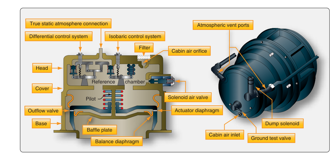
Every time a pressurized airliner or turboprop climbs to cruise altitude, the passengers inside experience something close to a comfortable mountain resort — perhaps 6,000 to 8,000 feet of cabin altitude — while the aircraft itself may be cruising at 35,000 feet or higher. The device that makes this possible is deceptively simple in concept: a valve that lets air out. The outflow valve is the primary exhaust point for the cabin pressurization system, and by controlling exactly how fast conditioned air leaves the fuselage, it governs cabin altitude, rate of pressure change, and differential pressure limits. Understanding how the outflow valve works — and how its automatic control logic operates — is fundamental knowledge for any AMT working on transport-category or pressurized general aviation aircraft.
The Pressurization System in Context
To appreciate the outflow valve's role, it helps to think of the pressurized fuselage as a leaky balloon that is continuously being inflated. Conditioned air — typically bleed air from the engines or, on newer aircraft, electrically compressed air — flows into the cabin at a controlled rate. If that air had nowhere to escape, pressure would build uncontrollably. The outflow valve is the primary intentional exit point, metering airflow out of the fuselage so that the cabin pressure stabilizes at the desired level. Safety relief valves also exist, but they are last-resort devices; the outflow valve is the system's normal pressure regulator.
Most transport-category aircraft use a pneumatic or electro-pneumatic outflow valve — a motorized or spring-and-servo-actuated butterfly or poppet valve typically located near the aft lower fuselage. Its position is continuously adjusted in response to signals from the pressurization controller, which compares actual cabin altitude and differential pressure to the programmed schedule.
How the Outflow Valve Works
Valve Mechanics
The physical valve mechanism varies by aircraft type, but the operating principle is consistent. The valve contains a movable element — a butterfly disc, a poppet disc, or a sliding plate — that can be positioned anywhere from fully closed (maximum pressure retention) to fully open (no pressurization). In normal operation the valve hovers in a partially open position, creating a controlled restriction that backs up cabin pressure to the desired level.
Actuation is usually accomplished by one of three methods: pneumatic actuators fed by cabin differential pressure or regulated bleed air, electric motors (often dual-wound for redundancy), or a combination of both. Many systems use the cabin-to-ambient differential pressure itself as a pneumatic signal — if differential pressure rises above a target, that pressure signal drives the valve more open, venting the excess. This creates a self-regulating feedback loop even without electrical power.
Automatic Pressure Controller Logic
The automatic pressurization controller — sometimes called the cabin pressure controller or CPC — is the brain of the system. On modern aircraft it is a digital unit; on older designs it is a pneumatic-mechanical analog device. Regardless of technology, it performs the same core functions:
- Cabin altitude scheduling: The controller programs cabin altitude as a function of aircraft altitude, following a pre-calculated schedule so cabin altitude climbs gradually during ascent and returns to field elevation during descent. This keeps the rate of pressure change within passenger comfort limits — typically no more than 300–500 feet per minute of cabin altitude change.
- Differential pressure limiting: The controller monitors the difference between cabin pressure and outside ambient pressure. It prevents this differential from exceeding the aircraft's structural design limit — commonly expressed as a maximum positive differential (e.g., 8.6 psid on many transport jets) and a small negative differential limit (typically around 0.5 psid or less) that prevents outside air pressure from exceeding cabin pressure during rapid descent.
- Isobaric control: During cruise, once the cabin reaches its target altitude, the controller holds it there — isobaric mode — by making small, continuous outflow valve corrections to compensate for changes in conditioned airflow, leakage rates, or temperature-driven volume changes.
Feedback and Sensing
The controller uses cabin pressure sensors (absolute pressure transducers or aneroid capsules) and sometimes a cabin altitude rate sensor to determine whether the valve should move toward open or closed. The comparison is continuous. If cabin altitude is rising too fast — meaning cabin pressure is falling too quickly — the controller signals the outflow valve to close slightly, reducing the escape rate and allowing conditioned airflow to rebuild pressure. If cabin altitude is stable but differential pressure is approaching its maximum structural limit, the controller overrides the schedule and opens the valve to shed excess pressure regardless of cabin altitude target.
Isobaric vs. Differential Pressure Control Modes
Understanding the two primary operating modes clarifies why the outflow valve moves differently at different phases of flight. During isobaric mode — typically used from initial climb through cruise — the outflow valve modulates to hold a constant cabin altitude as the aircraft climbs. Early in the climb, outside pressure is still relatively close to cabin pressure, so the valve stays fairly open. As the aircraft climbs higher, the valve progressively closes to retain more air and maintain that target cabin altitude against the rapidly decreasing ambient pressure.
Once the aircraft's altitude requires more differential pressure than the structural maximum allows, the system switches to differential pressure control mode. Now the controller holds the differential constant at its maximum design limit rather than holding cabin altitude constant. This means cabin altitude will slowly rise as the aircraft climbs higher, but it will do so safely within structural limits. The outflow valve in this mode modulates to maintain that fixed differential rather than a fixed cabin altitude.
During descent, the process reverses. The controller schedules a gradual reduction in differential pressure, and the outflow valve opens progressively. The rate of cabin altitude decrease (pressure increase) must be managed carefully — a too-rapid descent can cause passenger ear pain and in extreme cases structural loading issues if negative differential builds up. The negative pressure relief valve handles any inadvertent negative differential, but the outflow valve's controlled opening during descent is the primary defense.
Redundancy and Manual Override
Because loss of pressurization control is a serious safety event, outflow valve systems incorporate multiple layers of redundancy. Many aircraft have two outflow valves or a primary outflow valve with a backup. The actuator often has dual motor windings powered from separate electrical buses. If the automatic controller fails, a standby controller or manual mode allows the flight crew to position the valve directly, typically through a toggle switch that drives the valve motor open or closed. In full manual mode the pilot monitors cabin altitude and differential pressure gauges and adjusts the valve position manually — a workload-intensive backup that underscores why the automatic system's reliability matters.
Safety relief valves are separate, spring-loaded devices set to open automatically if differential pressure exceeds the structural limit — they are not controlled by the pressurization controller and require no electrical power. They serve as the last line of defense and do not substitute for the outflow valve in normal operations.
Why It Matters for the AMT
From a maintenance perspective, the outflow valve is an item that demands careful inspection and rigging. A valve that sticks in the closed position can cause uncontrolled pressure buildup, potentially opening safety relief valves or, in a worst case, imposing structural loads beyond design limits. A valve that hangs open or leaks excessively will cause the system to lose cabin pressure at altitude, requiring crew to initiate emergency descent procedures. Seal condition, actuator motor current draw, valve travel and end-stop rigging, and controller calibration are all items addressed in the aircraft maintenance manual (AMM) at prescribed intervals.
When troubleshooting pressurization complaints — slow cabin pressurization, cabin altitude fluctuations, or failure to reach target cabin altitude — the AMT should always verify outflow valve operation early in the diagnostic process. A partially stuck valve, a failed position feedback sensor, or a malfunctioning controller can all produce similar symptoms. Ground testing with the aircraft on the ground using a pressurization test set, per the AMM procedure, allows valve travel and controller response to be verified safely.
Key Numbers and Rules
- Maximum cabin altitude for transport-category aircraft during normal operations is generally 8,000 feet MSL, per 14 CFR Part 25 airworthiness standards for crew and passenger comfort and oxygen requirements.
- Typical maximum positive differential pressure on large transport jets ranges from approximately 7.5 to 9.0 psid, depending on aircraft design; the exact value is specific to each aircraft type certificate.
- Negative differential pressure limits are much smaller — often 0.5 psid or less — because the fuselage skin is not designed to be loaded inward to the same degree as outward.
- Comfort-based cabin altitude change rates are generally kept below 300–500 feet per minute during normal pressurization scheduling.
- Outflow valve rigging, seal inspections, and controller functional checks must be performed in accordance with the applicable Aircraft Maintenance Manual (AMM) and any applicable Airworthiness Directives.
- Safety relief valves are separate from the outflow valve and are set to open at or slightly above the maximum positive differential pressure limit to protect fuselage structure.
Common Test Traps
- Outflow valve vs. safety relief valve confusion: The outflow valve is the active, controlled pressure regulator. The safety relief valve is a passive, last-resort device. Exam questions may try to blur this distinction — remember that the outflow valve modulates continuously; the safety relief valve opens only when structural limits are threatened.
- Valve position during climb: Students sometimes assume the outflow valve closes completely during climb. In fact it modulates — partially open throughout — progressively closing as the aircraft climbs higher and differential pressure grows.
- Cabin altitude vs. aircraft altitude: The controller regulates cabin altitude, not aircraft altitude. These are different values, and confusing them leads to errors when answering questions about what triggers a mode change or a warning.
- Isobaric mode transition: The switch from isobaric to differential pressure control is triggered by reaching the structural differential limit, not by a specific aircraft altitude. Different aircraft types hit this transition at different altitudes depending on their design differential.
- Manual mode workload: In manual mode the pilot or AMT directly drives the valve motor — there is no automatic cabin altitude regulation. Exam questions testing understanding of manual pressurization may ask what must be monitored and adjusted continuously.