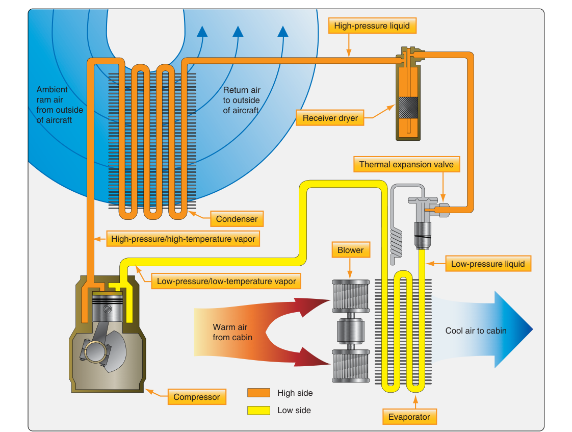
Aircraft cabin comfort depends on more than pressurization and fresh air. On many general aviation and transport-category aircraft, a vapor cycle air conditioning system (sometimes called a vapor cycle cooling system or VCS) provides the active refrigeration needed to remove heat from cabin air. Understanding how this system works — component by component — is essential knowledge for the Aviation Maintenance Technician (AMT) working on airframe systems, and it is a heavily tested area on the FAA Airframe Knowledge Test.
A vapor cycle system is a closed-loop refrigeration circuit. It moves heat from inside the cabin to the outside atmosphere by repeatedly changing a refrigerant between liquid and vapor states. The physics behind this is straightforward: when a liquid evaporates, it absorbs large amounts of heat from its surroundings; when a vapor condenses back to liquid, it releases that heat elsewhere. The four major components of the system orchestrate this phase-change cycle continuously while the system operates.
The Four Major Components and How Each Works
1. Compressor
The compressor is the mechanical heart of the vapor cycle system. Its job is to draw in low-pressure refrigerant vapor from the evaporator and compress it to a high-pressure, high-temperature vapor. Compression raises both the pressure and the temperature of the refrigerant, which is necessary so that the refrigerant can give up its heat to ambient air in the next stage. On reciprocating and turboprop aircraft, the compressor is typically belt-driven or engine-driven; on larger transport aircraft it may be electrically or pneumatically driven. The compressor must receive only vapor — never liquid refrigerant — because liquid is incompressible and will cause catastrophic mechanical damage, a condition called slugging. This is why the evaporator and any suction-line accumulator must ensure full vaporization before the refrigerant reaches the compressor inlet.
2. Condenser
From the compressor, the hot high-pressure vapor travels to the condenser. The condenser is a heat exchanger — typically located in a ram air duct on the aircraft exterior or in an area exposed to outside airflow — where the refrigerant releases its heat to the ambient air and condenses from vapor into a high-pressure liquid. Think of the condenser as the component that dumps heat overboard. The efficiency of the condenser depends heavily on airflow across its fins and coils, which is why many installations include a condenser fan that operates whenever the aircraft is on the ground and ram airflow is insufficient. If condenser airflow is blocked or the ambient temperature is extremely high, system head pressure rises and the system may cut out on a high-pressure switch to prevent damage.
3. Expansion Device (Expansion Valve or Orifice Tube)
After leaving the condenser as a high-pressure liquid, the refrigerant passes through the expansion device. This component creates a sudden, controlled pressure drop that causes the refrigerant to partially flash into vapor and drop dramatically in temperature — a process governed by the same thermodynamic principle that makes an aerosol can feel cold when you spray it. The two most common expansion devices found on aircraft systems are:
- Thermostatic Expansion Valve (TXV or TEV): A modulating valve that senses the temperature and pressure of the refrigerant leaving the evaporator (via a remote sensing bulb and an external equalizer line) and adjusts the flow of refrigerant to keep the evaporator operating at maximum efficiency without allowing liquid to reach the compressor. The TXV automatically compensates for varying heat loads and is the most common type on aircraft installations.
- Fixed Orifice Tube: A simpler, fixed-size restriction that does not truly meter flow at a constant rate — actual flow through it varies with the pressure differential across it as system conditions change. It is less precise than a TXV but has fewer moving parts and lower maintenance complexity. Because a fixed orifice tube cannot regulate flow the way a TXV does, these systems require a separate accumulator on the low side (rather than a receiver-drier) to trap unvaporized liquid before it reaches the compressor. Many automotive-derived aircraft air conditioning systems use this type.
After the expansion device, the refrigerant is a cold, low-pressure mixture of liquid and vapor — ready to absorb cabin heat in the evaporator.
4. Evaporator
The evaporator is mounted inside the aircraft in the cabin air duct or a dedicated plenum. Warm cabin air is blown across the evaporator coils by a blower fan. As the cold low-pressure refrigerant flows through the coils, it absorbs heat from the cabin air and vaporizes completely, becoming a low-pressure vapor. This is the step that actually cools the cabin — heat is transferred from the cabin air into the refrigerant. The now-warm vapor exits the evaporator and returns to the compressor inlet to begin the cycle again. A secondary benefit of the evaporator is dehumidification: because the coil surface temperature is typically below the dew point of cabin air, moisture condenses on the evaporator fins and drains overboard, reducing cabin humidity and preventing window fogging.
Supporting Components
Beyond the four primary components, several supporting elements are essential to safe and efficient operation:
- Receiver-Drier (Filter-Drier): Located in the liquid line between the condenser and the expansion valve, this component serves as a reservoir for liquid refrigerant, removes moisture with a desiccant, and filters contaminants. Moisture in a refrigeration system can combine with refrigerant to form acids that corrode components and can freeze at the expansion valve, blocking flow. The receiver-drier must be replaced whenever the system is opened to atmosphere.
- Sight Glass: Often built into the receiver-drier or liquid line, the sight glass allows a technician to visually inspect refrigerant flow. A clear, bubble-free sight glass indicates adequate refrigerant charge. Bubbles indicate low charge or moisture; foamy refrigerant suggests a severely undercharged system.
- High-Pressure and Low-Pressure Switches (Protective Switches): These safety switches shut down the compressor if system pressures exceed safe limits. The high-pressure switch protects against condenser blockage or overcharge; the low-pressure switch protects against loss of refrigerant charge or excessively cold evaporator temperatures that could freeze the evaporator coil solid and block airflow.
- Suction Line Accumulator: Some systems include an accumulator on the low-pressure side between the evaporator and the compressor to trap any liquid refrigerant that was not fully vaporized in the evaporator, preventing slugging of the compressor.
Refrigerants Used in Aircraft Systems
Older aircraft systems used R-12 (dichlorodifluoromethane, a chlorofluorocarbon or CFC) as the refrigerant. Under the Montreal Protocol and implementing EPA regulations, new production of virgin R-12 for most uses was phased down and largely ended in the United States by the mid-1990s; reclaimed and recycled R-12 has continued to be used for servicing existing systems. Many aircraft systems have since transitioned to R-134a (tetrafluoroethane, an HFC). These refrigerants are not interchangeable — system seals, lubricating oils, and component materials are specific to the refrigerant type. Always verify the correct refrigerant type from the aircraft manufacturer's maintenance manual before servicing a system.
Why It Matters for AMTs
A thorough understanding of vapor cycle components is not just academic — it directly guides troubleshooting. If cabin cooling is insufficient, a technician must systematically evaluate: Is the compressor engaging and building head pressure? Is the condenser receiving adequate airflow? Does the sight glass show adequate charge? Is the TXV opening properly? Is the evaporator coil iced over due to a failed low-pressure switch? Each symptom points to a specific component. Misdiagnosing a low refrigerant charge as a compressor failure — or vice versa — leads to unnecessary part replacement and continued system malfunction.
Key Numbers and Rules
- The high side of the system (compressor outlet to expansion device inlet) carries high-pressure, high-temperature refrigerant.
- The low side (expansion device outlet to compressor inlet) carries low-pressure, low-temperature refrigerant.
- The receiver-drier must be replaced any time the system is opened to the atmosphere, regardless of how briefly.
- Refrigerant types R-12 and R-134a are not interchangeable; always consult the maintenance manual for the correct type and charge weight.
- A bubbling or foamy sight glass indicates low refrigerant charge or moisture contamination.
- The compressor must never ingest liquid refrigerant — only fully vaporized refrigerant should enter the compressor inlet.
- Condenser fan operation is critical on the ground when ram air velocity is insufficient to provide adequate heat rejection.
Common Test Traps
- Mixing up high-side and low-side components: The FAA test may ask which components are on the high-pressure side versus the low-pressure side. Remember: compressor and condenser are high-side; evaporator and suction line are low-side. The expansion device is the dividing point.
- Receiver-drier replacement: Many students overlook the rule that the receiver-drier must be replaced whenever the system is opened, not just when it fails. Any exposure to atmospheric moisture saturates the desiccant.
- What the sight glass actually indicates: A clear sight glass with no bubbles is good. Bubbles do NOT mean the system is working correctly — they indicate low charge. Do not confuse a clear sight glass with a full charge until pressures are also verified.
- Compressor slugging: The test may describe symptoms of a compressor damaged by liquid refrigerant. Recognize that slugging is caused by liquid entering the compressor and that the accumulator and TXV are the primary safeguards against this.
- Refrigerant interchangeability: The FAA tests the knowledge that different refrigerants require different oils and components. Never assume refrigerants can be substituted without full system conversion per the manufacturer's data.