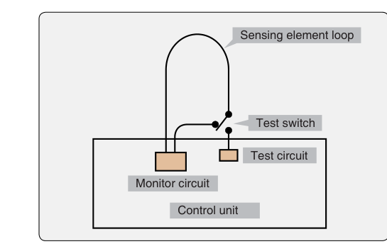
Aircraft fire detection systems are among the most safety-critical circuits on any airframe. A single undetected fault — a broken wire, corroded connector, or shorted sensing element — can leave the flight crew blind to a real fire or, conversely, bombard them with nuisance warnings that mask the genuine alarm. For the aviation maintenance technician (AMT) working toward an Airframe certificate, understanding how to isolate faults and verify loop integrity in these systems is not simply an academic exercise; it is a core maintenance task governed by the aircraft manufacturer's maintenance manual and the general standards found in FAA guidance. This article walks through detector types, the principles behind loop testing, specific fault isolation strategies, and the practical pitfalls that appear on the FAA Airframe Knowledge Test.
Fire detection systems fall into two broad categories: spot-type detectors, which respond to heat or optical phenomena at a single discrete point, and continuous-loop systems, which sense heat along the entire length of a sensing element routed through engine nacelles, wheel wells, or cargo compartments. Because continuous-loop systems are far more common on turbine-powered transport and business aircraft, the majority of fault-isolation work — and the majority of AMT exam questions — centers on them. However, spot-detector circuits appear on smaller piston aircraft and supplemental systems, so both deserve thorough treatment.
Types of Fire Detection Systems and Their Sensing Elements
Spot-type thermal detectors include bimetallic (thermocouple) units and rate-of-rise detectors. A thermocouple detector works on the principle that dissimilar metals joined at two junctions produce a voltage proportional to the temperature difference between those junctions. During a rapid temperature rise, the hot junction (exposed to the fire environment) heats faster than the reference junction, generating enough millivoltage to trigger the alarm relay. A rate-of-rise detector adds a mechanical diaphragm or electronic differentiator that trips only when temperature increases beyond a preset rate, helping to avoid false alarms from slow, normal heat buildup.
Continuous-loop systems use a long, flexible sensing element — essentially a coaxial tube or twisted-pair conductor — filled with a eutectic salt or a thermistor material whose electrical resistance drops dramatically as temperature climbs. The two most common designs used in commercial aviation are the Kidde (thermistor-type) system and the Fenwal (eutectic-salt) system, though both manufacturers have produced multiple sensing technologies over the years, so AMTs should always consult the specific aircraft maintenance manual (AMM) for system identification and test procedures rather than assume system type from manufacturer name alone. In both designs, the sensing element is connected to a control unit that monitors the electrical characteristics of the loop continuously.
How Loop Integrity Works
The word integrity in this context means that the sensing loop is unbroken, properly terminated, and within resistance specifications so that the control unit can distinguish three distinct states: normal (no fire, circuit intact), fire alarm (resistance falls below the alarm threshold due to heat), and fault (an open circuit, a short to ground, or a resistance value outside normal range).
In a thermistor-type continuous-loop system, the control unit monitors the average and discrete resistance characteristics of the thermistor core to distinguish normal, overheat/fire, and fault conditions; the precise electrical excitation method used by a given control unit is manufacturer-specific and should be confirmed in the AMM rather than assumed. Under normal ambient temperatures, the thermistor material maintains a high resistance — typically in the range specified by the manufacturer, often tens of thousands of ohms. As temperature at any point along the loop rises to the alarm threshold, the local resistance drops sharply, and the total loop resistance falls below the alarm set-point, triggering the warning. An open-circuit fault removes current flow entirely, and the control unit interprets the loss of current as a fault (not a fire), illuminating a fault or loop-fault annunciator rather than the fire warning light. A short-circuit fault collapses the loop resistance immediately; in the Kidde thermistor-type system this is typically detected by the control unit as a fault rather than a fire warning, since fire detection relies on rate-of-change and average resistance patterns rather than a simple short — the specific response varies by system design, so this is a critically important distinction during fault isolation, because a mechanic who applies the wrong test voltage or misinterprets the annunciator could compromise a fault investigation while systems are powered.
In a eutectic-salt (Fenwal) system, a single center conductor is surrounded by eutectic salt inside an Inconel outer tube; at the alarm temperature the salt's resistance drops sharply rather than the salt literally melting to create direct metal-to-metal contact between the center conductor and the outer tube. The loop integrity check in this system verifies that the center conductor is not shorted to the outer tube at ambient temperature, that the outer tube has continuity along its length, and that connector resistance is within limits.
Fault Isolation Procedures
Before beginning any fault isolation, consult the AMM and the applicable wiring diagram. Safety the system per the AMM — in most cases this means pulling the fire detection circuit breaker and, on aircraft with pressurized bottles, following the lockout/tagout procedures for the agent release circuits so that a false alarm cannot discharge a suppression agent.
Step 1: Identify the Fault Type
The first step is determining whether the system is indicating a fault/loop fault or a spurious fire warning. A loop-fault indication points toward an open circuit, while a spurious fire warning (with no actual fire) on the ground most commonly points toward a short to ground or a sensing element that has been kinked, chafed, or crushed. Document the annunciator state before pulling power.
Step 2: Segment the Loop
Most continuous-loop installations allow the sensing element to be disconnected at intermediate junction boxes or connector breakpoints along the engine nacelle or fuselage. By disconnecting the loop at the midpoint and measuring resistance from each end back to the control unit connector, the technician can determine which half of the loop contains the fault. Continue bisecting the loop until the faulty segment is isolated to a manageable section — this is the classic halving method of fault isolation used throughout aircraft electrical troubleshooting.
Step 3: Resistance Measurement
Use a calibrated digital multimeter (DMM) on the ohms setting. Measure resistance across the sensing element terminals at the control unit connector with the sensing element disconnected from the unit. Compare measured values against the manufacturer's resistance specifications. A reading of infinite resistance (OL) confirms an open circuit. A reading of near-zero ohms confirms a short. A reading within the specified range but outside normal ambient-temperature expectations suggests partial contamination, moisture ingress into a connector, or a pinched element that has not yet fully shorted.
Step 4: Insulation Resistance Check
After locating the suspect segment, perform an insulation resistance (megohm) test per the AMM using a calibrated megohmmeter at the voltage level the manufacturer specifies — using an incorrect test voltage can permanently damage the sensing element material. The insulation resistance between the center conductor and the outer sheath should meet the minimum megohm value in the AMM; a significantly lower reading indicates moisture, contamination, or physical damage to the dielectric material.
Step 5: Visual and Physical Inspection
Resistance data guides you to the area; then your eyes and hands confirm the finding. Inspect the sensing element for visible kinks, abrasion against structure, missing clamps that allowed chafing, cracked outer sheath, or signs of impact damage. Check connectors for corrosion, backed-out pins, or damaged sealing grommets that allow moisture intrusion. Even tiny amounts of contamination in a high-humidity environment can reduce insulation resistance enough to cause a false alarm.
Why Fault Isolation and Loop Testing Matter
A fire detection system that has a latent open-circuit fault will not alarm during an actual fire — a condition that could be catastrophic. Conversely, a system with repeated false alarms conditions crews to distrust the system, which is equally dangerous. FAA regulations under 14 CFR Part 25 (airworthiness standards for transport-category aircraft) require that fire detection systems be reliable and able to detect a fire rapidly. Maintenance standards under 14 CFR Part 43 require that any maintenance affecting airworthiness be performed to the manufacturer's standards and returned to an airworthy condition. Loop integrity testing is the primary method by which an AMT verifies that both requirements are met after any work in a fire zone.
Key Numbers and Rules
- Alarm threshold: Manufacturer-specific; always consult the AMM. Do not substitute generic values from training materials.
- Open circuit: Infinite resistance (OL on DMM) — system indicates a fault, not a fire warning, in most designs.
- Short circuit: Near-zero resistance — the resulting annunciation (fault vs. fire warning) depends on the specific system design (e.g., Kidde vs. Fenwal); always confirm the expected response in the AMM, and any confirmed short must be corrected before flight.
- Insulation resistance testing: Use the megohm voltage level specified in the AMM; incorrect voltage damages thermistor material.
- 14 CFR Part 43: Governs maintenance standards; work must restore the system to its original or properly altered condition.
- 14 CFR Part 25.858 / 25.859: Airworthiness standards requiring fire detection in engine, APU, and cargo compartments on transport-category aircraft.
- Continuity test: Verifies the circuit is unbroken but does NOT verify insulation integrity — both tests are typically required.
- False fire warnings from shorts: A common cause is chafing of the sensing element against structure; always inspect clamps and grommets after any maintenance in a fire zone.
Memory Aid
For loop fault isolation, use the acronym OTIC to remember the sequence: Open or short identification → Terminate (disconnect) and segment → Isolate the fault by halving → Confirm with insulation resistance and visual inspection. While OTIC is a practical workflow mnemonic rather than an FAA-official one, it maps directly to the steps described in most aircraft maintenance manuals and helps you stay organized under the pressure of a real troubleshooting task.
Common Test Traps
- Open circuit = fault, not fire: Many students assume that any abnormal condition causes a fire warning. In most continuous-loop systems, an open circuit causes a fault/loop fault indication, not a fire warning. Know which condition produces which annunciator.
- Short circuit response varies by system: Do not assume a short to ground always produces a fire warning. In the Kidde thermistor-type system a short is typically detected as a fault, while behavior in a Fenwal eutectic-salt system differs; always confirm the specific system's logic in the AMM, and remember that chafed sensing elements can generate spurious indications either way.
- Wrong test instrument voltage: Using a standard 500 V or 1,000 V megohmmeter on a sensing element rated for a lower test voltage can permanently damage the element. Always use the AMM-specified voltage.
- Continuity ≠ integrity: A loop can show continuity (unbroken circuit) while still having degraded insulation resistance. Passing only a continuity test and returning the aircraft to service without an insulation resistance check is an incomplete and potentially dangerous sign-off.
- Forgetting to re-torque and re-clamp: After reconnecting sensing element sections, students often overlook verifying that all clamps, bonding jumpers, and connector locking rings are restored. A loose connector or missing clamp after a loop integrity test is itself a maintenance-induced fault.