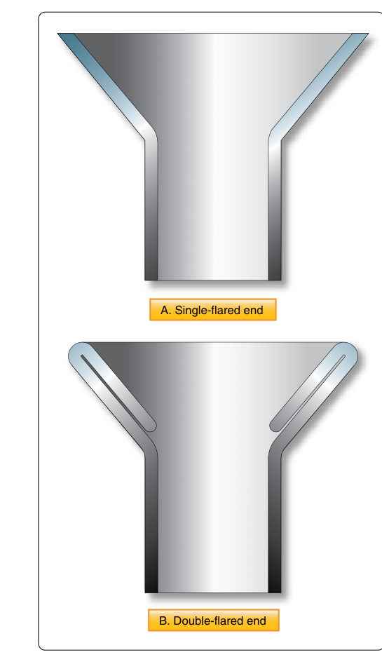
When an aircraft technician fabricates or repairs a hydraulic, fuel, oil, or brake fluid line, the job is rarely finished when the tube is cut to length. The tube end must be shaped — flared — so that it seats tightly against a mating fitting and creates a leak-free, mechanically secure joint. Two distinct flare profiles are used in aircraft maintenance: the single flare and the double flare. Knowing when each is required, how each is produced, and what can go wrong during fabrication is tested on the AMT General knowledge exam and, more importantly, is directly tied to flight safety.
This article walks through the geometry of each flare type, the tooling and step-by-step process for creating each, the material and application rules that govern which you must use, and the quality-inspection criteria that separate an airworthy tube end from a scrap piece.
Flare Basics: What a Flare Actually Does
A flare is a cone-shaped bell mouth formed at the end of a metal tube by pressing the tube material outward with a mandrel or punch. When the fitting nut is tightened, it drives this flared lip against a matching conical seat on the fitting body. The flared material is compressed between the nut and the fitting seat, creating a metal-to-metal seal. No gasket is required. The quality of that seal depends entirely on the uniformity, dimensions, and surface finish of the flare — a wrinkled, cracked, or off-center flare will leak under pressure or fatigue and crack with vibration.
Single-Flare Construction
A single-flare, also called a 37-degree flare in aircraft applications (as distinguished from the 45-degree flare used in automotive/SAE practice), is formed by pressing a cone-shaped mandrel directly into the end of the tube a single time. The result is a single-thickness bell that flares outward to match the fitting seat — the AN/MS standard specifies a 37-degree included angle for the cone (approximately 18.5 degrees measured from the tube centerline as the half-angle), producing the characteristic shape that mates with AN fittings.
The single-flare process uses a flaring tool consisting of a clamp block with holes sized for common tube outside diameters and a yoke-mounted cone. The tube is inserted through the clamp until it protrudes by an amount equal to the height of the flare to be formed — typically the depth of the chamfer in the clamp block acts as a guide. The cone is then driven into the tube end by threading the handle down, cold-working the metal outward in one pass.
Single flares are used on larger-diameter tubing and on harder materials such as stainless steel, titanium, and aluminum alloy tubing above certain wall thicknesses. They are also the standard for AN/MS fittings throughout aircraft hydraulic, fuel, and oil systems when the tube material and diameter are appropriate. However, single flares on thin-wall soft tubing can split or produce uneven walls, which is why the double flare was developed.
Double-Flare Construction
A double flare, sometimes called a double-inverted flare, is produced in two distinct tool operations. First, a special adapter — a small cylindrical punch with a stepped tip — is placed inside the tube end and the yoke is pressed down, rolling the protruding tube material inward and back over itself. This folds the tube wall in on itself, doubling its thickness. In the second operation, the adapter is removed and the standard cone is pressed down to finish-flare the now-doubled material outward to the final 37-degree included-angle seat.
The result is a flare with twice the wall thickness at the sealing face compared to a single flare. This doubled material is far more resistant to cracking under vibration and repeated pressure cycling, and it forms a more uniform, smoother seating surface. These properties make the double flare the required choice for soft aluminum tubing of small outside diameter — typically 3/8 inch outside diameter and under — because thin-wall aluminum is prone to splitting when single-flared. The double flare distributes forming stresses and leaves a much more robust lip.
The double-flare tool set includes the same clamp block as a single-flare tool but adds a set of adapter inserts, one for each tube size, that perform the initial inward fold. The tube must protrude from the block by a precise amount — too little and the fold will be incomplete, too much and the fold will be oversized and misshapen. Most quality tool sets include a gauge or the clamp depth is marked for each size.
Which Flare to Use: Rules and Applications
The choice between single and double flare is not left to technician preference — it is dictated by the tube material, outside diameter, and the applicable specification or maintenance manual.
- Single flare (37-degree AN/MS standard): Required for most aircraft hydraulic, fuel, and oil lines using AN or MS fittings, particularly on aluminum tubing larger than 3/8 inch OD, and on all stainless steel and titanium tubing. Also used when the fitting itself is designed only for a single-flare seat.
- Double flare: Required for soft aluminum (5052-O or 6061-T4) tubing in small diameters, generally 3/8 inch OD and smaller, and for automotive-heritage brake lines that use the double-inverted standard. The FAA Aircraft Maintenance Manual system and MIL-SPEC standards specify this for these applications.
- Never mix flare types with incompatible fittings. A double flare seated against a fitting machined for a single-flare cone will not seal correctly and may fail under pressure. Always verify fitting and tube compatibility before assembly.
- MS flareless fittings are a third category entirely — they use a sleeve (ferrule) that bites into the tube OD rather than a flared end, and they require their own special pre-swaging or pre-assembly procedure. Do not confuse them with flared-tube fittings.
Step-by-Step Fabrication Quality
Regardless of flare type, the tube must be prepared correctly before forming begins. The tube is cut with a tube cutter (not a hacksaw, which leaves burrs and work-hardening), deburred inside and outside with a reamer or deburring tool, and cleaned. The fitting nut must be slipped onto the tube before flaring — a mistake that wastes a perfectly good tube if forgotten. The tube is then secured in the correctly sized hole in the clamp block with the proper protrusion, and the flare is formed slowly with steady, even pressure.
After forming, the completed flare is inspected visually and dimensionally. Acceptable flares are smooth, concentric, and free of cracks, splits, or wrinkles. The flare diameter must be within the tolerance specified for the tube size — too small and the fitting seat will not be fully contacted; too large and the flare lip will fold when the nut is tightened. The seating face must be free of tool marks deep enough to create leak paths. Any flare that shows a crack — even a hairline — must be cut off and re-flared or the tube replaced.
Why It Matters: Safety and System Integrity
Fluid lines in aircraft operate under sustained pressure, temperature cycling, and vibration. A compromised flare can fail gradually — weeping a slow fuel or hydraulic leak — or catastrophically under a pressure surge. Hydraulic system pressures in general aviation aircraft commonly run 1,000 to 3,000 psi, and turbine aircraft systems can reach 5,000 psi or more. Even a small crack in a flare is not a maintenance-deferred item; it is an airworthiness defect. Brake line failures due to cracked double-flares have contributed to runway excursion accidents, making correct fabrication technique an immediate safety concern, not an academic one.
Key Numbers and Rules
- 37-degree flare angle — the standard included angle for AN/MS aircraft flared fittings (the cone angle that mates with AN fittings).
- 3/8 inch OD and smaller — general threshold below which soft aluminum tubing typically requires a double flare.
- Two operations — a double flare always requires two separate tool strokes: the inward fold, then the outward cone press.
- Nut first — the fitting nut must always be installed on the tube before the flare is formed; there is no way to add it afterward.
- No hacksaw cuts — tube cutters preserve tube roundness and minimize work-hardening at the cut; hacksaws are not acceptable for aircraft tubing.
- Zero cracks accepted — any cracking of the flare surface is cause for rejection regardless of flare type or tube material.
Common Test Traps
- Confusing the flare angle: The FAA written test may list 45 degrees as the standard aircraft flare angle, but the correct AN/MS standard is 37 degrees. Do not let the more familiar automotive 45-degree figure mislead you.
- Assuming single flares are always stronger: Single flares on small-diameter soft tubing are actually more prone to cracking than double flares; the double flare is the safer choice for thin-wall aluminum in small sizes.
- Forgetting the nut: Test questions may present a scenario where the nut was installed after flaring — recognize this as a required re-fabrication, not a problem that can be worked around.
- Mixing flare types with wrong fittings: A question may ask whether a double-flared tube can be used with a standard AN single-flare fitting. The answer is no — incompatible seat geometry means improper sealing.
- Overlooking surface defects: Test scenarios sometimes describe a flare with minor tool marks or a slight wrinkle and ask if it is airworthy. Unless the defect is truly cosmetic and within specification, the correct answer is to reject and re-flare.