Flexible hose is a critical component in virtually every aircraft fluid system, allowing movement between airframe structures, accommodating vibration, and routing lines through areas where rigid tubing would crack or fatigue. However, the hose itself is only as reliable as its end fittings — the hardware that transitions the flexible section into a threaded or flanged connection. Two fundamentally different approaches exist for terminating flexible hose: swaged fittings, which are factory-installed and permanently crimped onto the hose, and reusable fittings, which can be disassembled and installed in the field. Every AMT must understand how each type works, when to use each, how to inspect them, and the specific rules governing their correct installation.
Construction and Types of Flexible Hose
Before examining the fittings, it helps to understand what they attach to. Aircraft flexible hose is typically constructed in one of three categories: low-pressure hose (fabric-braid reinforced rubber, used for fuel, oil, and coolant lines), medium-pressure hose (one or two layers of wire braid over a rubber inner tube), and high-pressure hose (multiple spiral wire layers capable of handling higher hydraulic system pressures). The inner tube material — typically synthetic rubber or PTFE (polytetrafluoroethylene) — must be compatible with the fluid being carried. PTFE-lined hose is widely used in modern aircraft because it is chemically inert, tolerates a broad temperature range, and resists most aviation fluids. Always consult the specific pressure ratings and breakpoints published in the aircraft maintenance manual and the current FAA-H-8083-30 hose chart rather than relying on generalized psi figures.
Hose is sized by its dash number, which refers to the inside diameter (ID) in sixteenths of an inch. A -6 hose, for example, has a 3/8-inch inside diameter. When selecting replacement hose, the technician must match the dash size, pressure rating, temperature rating, and fluid compatibility to the original specification listed in the aircraft's maintenance manual.
Swaged (Permanently Crimped) End Fittings
Swaged fittings — sometimes called crimped fittings — are installed using a hydraulic or mechanical crimping machine that compresses a metal ferrule or socket permanently around the outer layer of the hose. The assembly is performed by the hose manufacturer or a qualified hose shop following precise tooling specifications for each hose-and-fitting combination.
The swaging process works by forcing the socket inward to grip the wire braid or outer cover of the hose, while simultaneously pushing the hose material against a serrated or tapered nipple inside the hose. This creates a three-point seal: the nipple seals against the inner tube, the swaged socket grips the reinforcement layers, and the geometry of the assembly prevents the hose from blowing off under pressure. The result is a fitting that is stronger than the hose itself when properly made.
Because the crimping dimensions are critical, swaged assemblies must be proof-pressure tested after manufacture — typically to twice the working pressure of the hose — before they are approved for installation. Many manufacturers certify each assembly with a serialized tag showing hose part number, assembly date, and proof-test results. The technician receiving a swaged hose assembly should verify this documentation matches the aircraft maintenance manual requirements before installation.
Identifying a Properly Swaged Fitting
A correctly swaged fitting will show the socket seated squarely and fully on the hose with no visible gap between the socket end and the hose cover. The crimp marks around the socket circumference should be uniform. Reject any assembly that shows the socket pulled back or separated from the hose, bulging of the inner tube at the fitting end, cracks in the outer cover near the socket, or corrosion pitting on the metal socket. Once a swaged fitting shows damage or leakage, the entire hose assembly is replaced — the fitting cannot be removed and reused.
Reusable End Fittings
Reusable fittings allow a qualified technician to cut the hose to length in the field and install the fitting without special crimping machinery. They are especially valuable for emergency repairs and for small shops that do not have swaging equipment. Reusable fittings are available for both low-pressure rubber hose and for some medium-pressure assemblies, but they are generally not approved for high-pressure or PTFE hose applications unless the manufacturer's data specifically permits it.
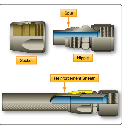
A typical reusable fitting consists of three parts: a socket (the outer shell that threads onto or over the hose end), a nipple (the internal serrated or barbed body that goes inside the hose), and the fitting body itself (which provides the AN, MS, or JIC threaded end that connects to the system). Installation follows a precise sequence:
- Cut the hose squarely using a fine-tooth saw or hose cutter — never a rotary pipe cutter, which will collapse the braid.
- If required for the hose type, strip the outer cover back approximately one inch to expose the braid.
- Place the socket onto the hose end and thread or push it on in the direction called out by the manufacturer.
- Lubricate the nipple with the fluid appropriate to the hose application (hydraulic fluid for hydraulic hose, clean engine oil for fuel hose — never use grease or silicone).
- Thread or push the nipple into the hose until the hose butts firmly against the nipple shoulder.
- Thread the socket back onto the nipple body and torque to the manufacturer's specification, which compresses the hose between the socket and the nipple serrations.
After assembly, inspect that the hose end is fully seated: no more than one thread of the nipple should remain visible between the socket and the fitting body (the exact number varies by manufacturer). Then perform a proof-pressure test or leak check per the maintenance manual before returning the line to service.
Why It Matters: Safety and System Integrity
A failed hose end fitting can result in rapid loss of hydraulic fluid — causing loss of flight controls or landing gear — or a fuel leak near an ignition source. Because flexible hose assemblies are not visible for much of their service life (they are often routed behind panels or through tight spaces), a fitting that is beginning to leak internally or that has a slightly pulled socket may go unnoticed until a catastrophic failure. This is why FAA and manufacturer guidance places such emphasis on proper assembly technique, torque values, and periodic replacement intervals.
Manufacturers and the FAA recommend replacing flexible hose assemblies at intervals specified by the aircraft or hose manufacturer, because the inner tube degrades over time even when the outside looks acceptable. There is no single universal calendar interval for rubber or PTFE hose; always verify against the specific aircraft maintenance manual and current airworthiness directives.
Key Numbers and Rules
- Dash number sizing: hose ID in sixteenths of an inch (e.g., -8 hose = 1/2-inch ID).
- Proof-pressure test: typically 2× the rated working pressure for swaged assemblies.
- Minimum bend radius: must not be violated during installation; too tight a bend collapses the inner tube and restricts flow or causes cracking — refer to the manufacturer's data for each hose type.
- Hose slack: flexible hose must never be installed in a taut straight line. Allow approximately 5–8% additional length to prevent the hose from pulling at the fittings when pressurized (hose shortens slightly under pressure) or when airframe flexes.
- Twist: hose must not be twisted during installation. Twist reduces burst pressure and is a common cause of premature failure. Alignment marks on the hose surface are used to verify zero twist after tightening.
- Reusable fitting lubrication: use the system fluid or clean engine oil — never aerosol lubricants, grease, or silicone compounds incompatible with the system fluid.
- Replacement interval: defer to the aircraft maintenance manual and applicable ADs — there is no single FAA-mandated calendar interval for all hose types.
Common Test Traps
- Confusing dash number with outside diameter: the dash number refers to the inside diameter in sixteenths of an inch, not the OD. Getting this backward leads to selecting the wrong replacement hose.
- Thinking reusable means re-swageable: a swaged fitting that has been removed or shows damage is scrapped along with the hose. Only fittings specifically designed as reusable can be reinstalled, and even then only if the nipple and socket threads are undamaged.
- Installing hose under tension: the FAA emphasizes that hose must have enough slack to accommodate pressurization (which shortens hose slightly) and airframe flexing. A taut hose is a failed hose waiting to happen.
- Ignoring twist: twist is the most common installation error with flexible hose. Even a small amount of twist measurably weakens the assembly. Many test questions describe a scenario with twisted hose and ask whether the installation is acceptable — it is not.
- Using the wrong lubricant during reusable fitting assembly: using an incompatible lubricant (especially silicone or petroleum grease in an oxygen line) can cause system contamination, fire, or seal degradation. Always match the lubricant to the system fluid.