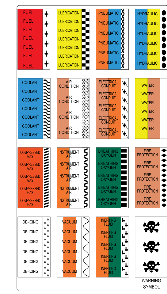
Walk through any aircraft maintenance hangar and you will quickly notice that the plumbing running through a fuselage or under a wing is rarely a single, anonymous color. Instead, fluid lines are marked with specific colors, geometric symbols, and letter abbreviations that form a universal language for aviation maintenance technicians (AMTs). Knowing how to read these markings is not merely a certification requirement—it is a daily safety practice that prevents a technician from accidentally cross-connecting a fuel line to a hydraulic return, or bleeding air into a system designed for liquid. The FAA Aircraft Maintenance Handbook and the standards referenced in MIL-SPEC and aerospace industry documents, as codified in FAA guidance, establish the system that every AMT must master.
This article breaks down the complete color-coding and identification marking system for aircraft fluid lines, explains how to apply and interpret each element, and highlights the test-relevant details you need to know for the FAA AMT General Knowledge Exam.
Why Standardized Marking Exists
Modern aircraft contain dozens of separate fluid systems operating simultaneously: fuel, engine oil, hydraulic fluid, pneumatic pressure, oxygen, water injection, fire-extinguishing agents, and more. Many of these lines run in parallel through the same conduit bundles or bilge areas, and some of the fluids themselves are clear or similarly colored liquids that are visually indistinguishable. A single wrong connection during a maintenance action could result in engine failure, fire, or loss of flight controls. Standardized markings eliminate ambiguity by giving each line a unique, instantly recognizable identity regardless of which aircraft model or which hangar you are working in.
The Three-Part Identification System
According to FAA guidance reflected in the Aviation Maintenance Technician Handbook—General (FAA-H-8083-30), aircraft fluid lines are typically identified by a combination of three elements working together:
- Color-coded tape or bands — a base color and, in many cases, a secondary color stripe or geometric design applied as a band around the line at regular intervals and at each end near a component or bulkhead fitting.
- Letter code abbreviations — printed directly on the tape or stenciled on the line to name the specific fluid or system (for example, FUEL, HYD, OIL, OXY).
- Geometric symbols — a shape such as a circle, square, diamond, or triangle that further classifies the line by its function within a system (supply, return, drain, vent, etc.).
Together, these three elements allow a technician to know, at a glance, both what is in the line and what the line does within its system. Some older aircraft use paint stenciling directly on the tubing rather than adhesive tape, but the color and symbol conventions remain the same.
Color Codes by System
The specific colors assigned to each system are standardized and must be memorized. The following list reflects the system established by MIL-STD-1247 and referenced in FAA maintenance training materials:
- Fuel — Brown. Fuel lines are among the most critical to identify correctly because fuel is both combustible and the lifeblood of the engine.
- Lubrication (Engine Oil) — Yellow. Oil lines carry both pressure and scavenge oil, and the geometric symbol differentiates supply from return.
- Hydraulic — Blue with a yellow stripe (or simply blue, depending on the specification version). Hydraulic systems operate at very high pressures, so correct identification is essential before any line is opened.
- Pneumatic (Compressed Air / Bleed Air) — Blue (a lighter or different shade from hydraulic, or differentiated by symbol and letter code). Some references use orange for high-pressure pneumatic and blue for low-pressure. Always confirm by the letter code (PNEU or AIR) in addition to color.
- Coolant (Engine Coolant or Liquid Cooling) — Yellow with a blue stripe or green, depending on the system and era of the aircraft. Verify with the letter code COOLANT.
- Fire Extinguishing — Brown with a white stripe. These lines carry halon or other suppression agents to the engine nacelle or cargo area.
- Oxygen — Green. Oxygen system lines are especially sensitive because oxygen vigorously supports combustion; connecting an oxygen line to any hydrocarbon-contaminated fitting can cause an explosion. The bright green color and OXY abbreviation together provide maximum warning.
- Water Injection — White. Some high-performance piston and turbine engines use water-methanol injection for power augmentation, and these lines must be clearly set apart from fuel lines.
- Instrument Air — Blue with a red stripe or orange. Instrument air systems supply gyroscopic instruments and must remain clean and dry.
- De-icing / Anti-icing Fluid — Gray or a gray-striped band, with the appropriate letter code.
It is important to note that color perception can vary slightly under poor lighting conditions in a bilge or behind a panel. This is exactly why the letter code provides a critical second layer of identification independent of color.
Geometric Symbols and Functional Meaning
Color tells you which system; the geometric symbol tells you what role the line plays within that system. The standard symbols include:
- Filled circle (solid dot) — Pressure (supply line carrying fluid under pressure to a component).
- Empty (open) circle — Return (fluid returning to the reservoir or sump at low pressure).
- Filled square — Vent or Drain (open to atmosphere or gravity drain).
- Filled triangle or diamond — Suction (line drawing fluid from a tank toward a pump).
For example, a blue band with a filled circle and the letters HYD tells a technician this is the hydraulic pressure supply line. An open circle on a yellow band marked OIL indicates the engine oil return (scavenge) line. Mixing up pressure and return lines during reassembly can cause immediate system failure upon engine start.
Where Markings Are Applied
Markings are not placed haphazardly. FAA maintenance guidance specifies that identification bands should appear:
- At each end of the line, as close to the connecting fitting as practicable (typically within 3 inches or less).
- At regular intervals along long runs—often every 3 feet (approximately every meter) in accessible areas.
- Immediately adjacent to each shutoff valve, filter, or component connection point, so the technician servicing that component can identify the line without tracing it back to its origin.
- Where lines pass through bulkheads or firewalls, markings appear on both sides of the penetration.
Key Numbers and Rules
- Markings are typically placed within 3 inches of each end fitting and at intervals no greater than every 3 feet along the run.
- The letter code, color band, and geometric symbol together form the complete identification—never rely on color alone, especially under artificial lighting.
- Oxygen system lines are green and must be kept completely free of oil and grease—even skin oils can create a combustion hazard in the presence of pressurized oxygen.
- Fuel lines are identified by brown; confusing a fuel line with a hydraulic line (blue) is one of the most dangerous cross-connection errors possible.
- Markings must be legible and securely attached; degraded or missing markings must be replaced before the aircraft is returned to service.
- On flexible hoses, the identification markings are typically applied as adhesive wrap-around bands rather than paint, because paint on a flex hose may mask cracks in the outer cover.
Common Test Traps
- Relying solely on color. The FAA exam often presents scenarios where color alone is ambiguous—for example, hydraulic and pneumatic lines may both appear blue. The letter code and geometric symbol resolve the ambiguity; always use all three identification elements together.
- Confusing oil and fuel colors. Oil lines are yellow; fuel lines are brown. Students sometimes mix these up because both involve petroleum products. Remember: brown for fuel, yellow for oil.
- Geometric symbol meaning. A filled circle means pressure, not just any connection. An open circle means return. The exam may ask you to interpret what a symbol means in the context of a hydraulic or oil system.
- Placement intervals. The exam may ask where markings must appear. Know that markings go within 3 inches of fittings, every 3 feet along the run, on both sides of a bulkhead, and adjacent to each servicing point.
- Oxygen line safety. Questions about oxygen systems frequently focus on contamination hazards. The green color and strict no-oil rule are both heavily tested. Never use oil-contaminated tools or fittings on an oxygen line.
Practical Takeaways for the Shop
When you are tracing an unfamiliar line in an aircraft, start at a known component—a reservoir, a filter bowl, or a pump—and read the markings at that end first. Confirm the letter code, verify the color, and note the geometric symbol. Then follow the line and confirm the markings are consistent and legible along its entire length. If any marking is missing, illegible, or contradictory, do not assume—consult the aircraft maintenance manual and replace the marking before proceeding.
Understanding this system deeply, not just memorizing it, is what separates a careful technician from a careless one. The color-coding and identification marking system is ultimately about one thing: making the right action obvious, every time, so that the aircraft and everyone who depends on it remains safe.