When an aircraft flies an Instrument Landing System (ILS) approach in low-visibility conditions, the flight crew must know — precisely and without ambiguity — where the aircraft is along the approach path at each critical moment. The marker beacon system provides exactly this positional awareness by transmitting narrow, fan-shaped radio signals vertically upward from fixed ground stations positioned at specific distances along the ILS course. As the aircraft flies through each beam, a receiver on board decodes the unique signal, illuminates a colored cockpit light, and drives an audio tone into the crew's headsets. Together these indications give an unmistakable, standardized announcement: you are crossing a specific fix, right now.
For the Aviation Maintenance Technician (AMT) working on airframe systems, a thorough understanding of the marker beacon receiver — its components, frequencies, signal characteristics, light indications, and inspection requirements — is essential for both the FAA Airframe Knowledge Test and safe, airworthy maintenance practice. This article covers the complete system from ground station physics through the cockpit annunciator panel and the maintenance tasks that keep it reliable.
Ground Station Signals and Aircraft Reception
All marker beacon transmitters operate on the same single carrier frequency: 75 MHz. Because every transmitter uses the same frequency, the receiver cannot use frequency alone to distinguish outer from middle from inner marker. Instead, each ground station modulates its 75 MHz carrier with a unique audio tone and keying pattern. The airborne receiver decodes these modulation signatures to identify which marker is being crossed.
- Outer Marker (OM): Modulated at 400 Hz with a continuous series of dashes (two dashes per second). The OM is normally located 4 to 7 nautical miles from the runway threshold, close to the point where the glide slope is intercepted at pattern altitude. It marks the approximate beginning of the final approach segment.
- Middle Marker (MM): Modulated at 1,300 Hz with an alternating dot-dash pattern. The MM is positioned approximately 3,500 feet from the runway threshold, corresponding roughly to the point on the glide slope about 200 feet above touchdown — the Category I decision height. It alerts the crew that the runway environment should be in sight, or a missed approach must be initiated.
- Inner Marker (IM): Modulated at 3,000 Hz with a rapid series of dots (six dots per second). Where installed, the IM is located at or near the runway threshold and is associated with Category II ILS operations. Not all ILS approaches have an inner marker.
The transmitting antenna at each ground station produces a figure-eight or fan-shaped radiation pattern oriented perpendicular to the runway centerline, so the beam is narrow along the approach path (typically only a few hundred to a few thousand feet in width, depending on altitude). The aircraft passes through the beam in a matter of seconds during a normal approach, producing a brief but distinct burst of audio and light that the crew associates with crossing that specific fix.
Airborne Receiver Components
The marker beacon receiver system on a typical transport or general aviation aircraft consists of several integrated elements.
The Receiver Unit
The receiver is a dedicated or combined VOR/ILS/marker beacon unit that is continuously tuned to 75 MHz when marker beacon functionality is active. It contains a bandpass filter centered on 75 MHz, followed by detector circuitry that extracts the audio modulation tone. The tone frequency is then compared against the three reference frequencies (400 Hz, 1,300 Hz, and 3,000 Hz) using additional bandpass filter stages. When the incoming tone matches one of these references with sufficient signal strength, the corresponding output is activated. Many modern receivers integrate the marker beacon function into a multifunction navigation receiver, but the fundamental circuit architecture is the same.
The Antenna
The marker beacon antenna is mounted on the underside of the fuselage to face downward toward the ground transmitters. It is a simple, low-gain antenna — often a small blade or loop type — specifically tuned to 75 MHz. Its position and orientation are critical: damage, improper bonding, or incorrect installation can reduce sensitivity and cause the receiver to fail to detect a marker, or to detect it only at very short range. The AMT should verify antenna condition, mounting hardware torque, and coaxial connector integrity during each inspection.
Cockpit Annunciator Lights
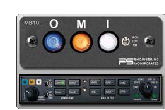
The most visible output of the marker beacon system is the set of colored lights on the instrument panel or dedicated annunciator panel. Three lights correspond to the three markers:
- Blue (Cyan) Light — Outer Marker: Illuminates when the 400 Hz tone is decoded. In some aircraft documentation and older installations this is described as blue, while in others it appears more cyan; the FAA standardizes it as blue. It flashes in synchrony with the dash keying pattern.
- Amber (Yellow) Light — Middle Marker: Illuminates when the 1,300 Hz tone is decoded. It flashes in the alternating dot-dash pattern of the MM transmission.
- White Light — Inner Marker (or Airways/Fan Marker): Illuminates when the 3,000 Hz tone is decoded. It flashes with the rapid dot sequence. The white light is also used to indicate passage over an airways fan marker or a back-course marker at some installations.
Each light flashes rather than illuminating steadily, and the flash rate matches the audio tone keying. This dual confirmation — light color plus flash pattern plus audio tone — makes the indication highly redundant and resistant to misidentification even in a high-workload environment.
Audio Output
The decoded audio tone is routed to the aircraft's audio panel or interphone system and delivered to the crew's headsets. Pilots typically set marker beacon audio to play automatically whenever a signal is received; a sensitivity switch (HIGH/LOW) allows selection of reception range. The HIGH position extends sensitivity and is useful for enroute airways fan markers, while the LOW (or TEST) position reduces sensitivity to limit the indication to only very close proximity to the transmitter — preferred on ILS approaches to ensure the light and tone indicate the precise crossing moment rather than an extended zone.
Sensitivity Switch and Its Importance
Most marker beacon receivers include a two-position sensitivity switch labeled HIGH/LOW or SENS. In the HIGH sensitivity position, the receiver activates earlier as the aircraft approaches the beam, giving a wider activation zone. In the LOW sensitivity position, the receiver requires a stronger signal — essentially requiring the aircraft to be closer to directly over the transmitter — giving a more precise indication of the fix. For ILS approaches, LOW sensitivity is the operationally preferred setting because it provides the sharpest, most accurate crossing indication. The HIGH setting is appropriate for identifying airways checkpoints using 75 MHz fan markers. The AMT must verify that this switch functions correctly in both positions during functional checks.
Why the Marker Beacon System Matters for Safety
The marker beacon system serves as a physical, position-based cross-check that is independent of the localizer and glide slope signals. Even if a crew is managing a partial panel or experiencing NAV receiver anomalies, the marker beacon receiver operates completely independently. Crossing the outer marker tells the crew they are established (or should be establishing) on the final approach course at the correct altitude. The middle marker is the critical decision point for Category I approaches — if the runway is not in sight when the amber light and alternating tone sound, a missed approach must be executed immediately. This timing function is so important that 14 CFR Part 91 operations specifications and instrument approach procedure design standards build around it.
From a maintenance perspective, a marker beacon system that fails to annunciate — or that annunciates intermittently — can create a serious safety hazard during actual IFR operations. An AMT who discovers a faulty receiver, a corroded antenna connector, or a burned-out annunciator lamp must ground the relevant system and document the discrepancy before releasing the aircraft for IFR flight.
Key Numbers and Rules
- Carrier frequency: 75 MHz (all markers use the same frequency)
- Outer Marker audio modulation: 400 Hz, dashes; light color: Blue
- Middle Marker audio modulation: 1,300 Hz, dot-dash; light color: Amber
- Inner Marker audio modulation: 3,000 Hz, dots; light color: White
- Outer Marker typical location: 4 to 7 NM from threshold
- Middle Marker typical location: approximately 3,500 feet from threshold
- Antenna location: bottom of fuselage, facing downward
- Sensitivity switch: LOW for ILS approaches, HIGH for airways fan markers
- Required equipment: marker beacon receivers must meet TSO-C35 standards for certified installations
Common Test Traps
- Confusing light colors: A very common error is swapping blue and amber. Remember: Blue = Outer (big/far away), Amber = Middle, White = Inner. Associate the cool blue color with the distant outer marker.
- Thinking each marker uses a different frequency: All three markers transmit on 75 MHz. The receiver identifies them by the audio modulation tone, not by tuning to different frequencies. A test question may try to lead you toward thinking the OM is on a different frequency.
- Sensitivity switch setting: Students often select HIGH for ILS thinking more sensitivity is always better. The correct operational answer is LOW sensitivity for ILS approaches to get the precise crossing indication.
- Antenna location: The marker beacon antenna is on the bottom of the fuselage because the ground stations transmit upward. Confusing it with a top-mounted ADF sense antenna or GPS antenna is a common trap.
- Inner marker availability: Not every ILS installation includes an inner marker. Assuming one will always be present — or that the white light must illuminate on every approach — is incorrect. Its presence depends on the specific approach design and Category.