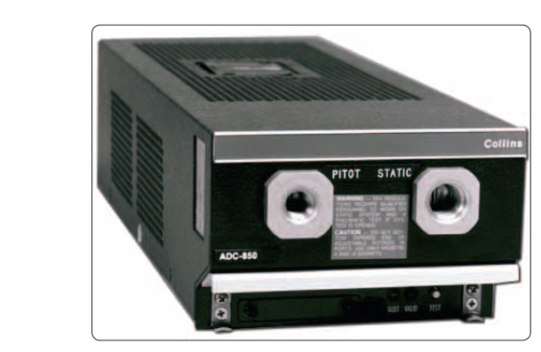
Modern transport-category aircraft rely on an Air Data Computer (ADC) to transform simple pressure and temperature measurements into the precise flight parameters pilots and automation systems need every second of flight. Rather than plumbing raw pitot-static air directly to individual gauges scattered across the cockpit, the ADC centralizes all air-data sensing into one smart, fault-monitored unit. Understanding what goes into the ADC, what comes out, and how errors are detected is essential knowledge for AMT Airframe candidates and for anyone who maintains or troubleshoots these systems.
The ADC fits within the broader category of Position and Warning Systems because its outputs directly feed attitude and heading reference systems (AHRS), flight management systems (FMS), autopilots, traffic collision avoidance systems (TCAS), ground proximity warning systems (GPWS/TAWS), and transponders. A fault in the ADC therefore has cascading effects across nearly every automated and safety-critical function on the aircraft.
Core Inputs to the Air Data Computer
The ADC is essentially a specialized processor that accepts a small number of raw physical signals and converts them into dozens of computed parameters. The primary inputs are:
- Pitot (Total) Pressure (PT): Ram air pressure sensed by one or more pitot probes mounted on the fuselage or nose. Pitot pressure represents the sum of static pressure plus dynamic pressure caused by the aircraft's forward motion through the air. Electrically heated pitot probes prevent ice blockage, and the ADC typically monitors the heater circuit as part of its built-in test equipment (BITE).
- Static Pressure (PS): Ambient atmospheric pressure sensed at flush static ports on the fuselage sides. Most transport aircraft use multiple static sources — typically one on each side of the fuselage — to minimize position error from sideslip or asymmetric airflow. The ADC may also accept an alternate static source signal if the pilot selects it.
- Total Air Temperature (TAT): Sensed by a TAT probe (also called a Kiel probe or stagnation temperature probe) mounted where it receives unobstructed airflow. At high speeds, aerodynamic heating raises the measured temperature above the actual outside air temperature. The ADC uses a recovery factor (a calibration constant specific to the probe design) to mathematically subtract the aerodynamic heating component and compute Outside Air Temperature (OAT), also called Static Air Temperature (SAT). TAT probes are also electrically heated, and the ADC monitors heater status.
- Angle of Attack (AOA) — on some installations: Certain advanced ADC designs accept a signal from a vane-type AOA sensor to refine stall warning computations or to cross-check computed airspeed. This is more common on military aircraft but appears on some newer transport designs.
All pressure inputs arrive at the ADC either through pneumatic tubing connected to pressure transducers inside the computer, or — in more modern solid-state designs — through remotely located pressure transducers (also called pressure sensors or MEMS sensors) whose electrical outputs are wired directly to the ADC. Solid-state systems eliminate long pneumatic lines, reducing the risk of moisture contamination and leaks.
What the ADC Computes: Key Outputs
Once the ADC receives its raw inputs, onboard algorithms apply the standard atmosphere model and aerodynamic equations to produce a rich set of computed outputs, distributed to other avionics and displays over digital data buses (ARINC 429 on most commercial aircraft, or the higher-speed ARINC 629 bus used on newer wide-body types such as the Boeing 777).
Airspeed-Related Outputs
- Indicated Airspeed (IAS): Computed from the differential between pitot and static pressure (impact pressure, qc). This is the airspeed that an uncorrected airspeed indicator would read. It is the starting point for pilot speed references.
- Calibrated Airspeed (CAS): IAS corrected for instrument and installation (position) error. The ADC stores correction tables derived during aircraft flight testing and applies them automatically.
- True Airspeed (TAS): CAS corrected for air density (altitude and temperature). The ADC computes TAS by dividing CAS by the square root of the density ratio, using static pressure and SAT. TAS is critical for flight planning, FMS ground-speed calculations, and wind computations.
- Mach Number (M): The ratio of TAS to the local speed of sound. The ADC computes Mach directly from the pressure ratio PT/PS using the isentropic flow equation, making it independent of temperature measurement errors. Mach is the primary speed reference at high altitudes and is used by the autopilot, autothrottle, and overspeed warning systems.
- Maximum Operating Airspeed (VMO/MMO) Comparison: The ADC continuously compares computed CAS and Mach to the aircraft's certificated limits and triggers an overspeed warning — a distinctive clacker or aural alert — when either limit is exceeded.
Altitude-Related Outputs
- Pressure Altitude: Computed from static pressure alone using the International Standard Atmosphere (ISA) equations. This is the altitude corresponding to a standard altimeter setting of 29.92 in Hg (1013.25 hPa), and it is the value transmitted to ATC via the Mode C/S transponder.
- Indicated (Baro-Corrected) Altitude: The pilot enters a local altimeter setting (QNH) into the flight deck, and the ADC (or the display unit) applies the barometric correction to pressure altitude to produce the altitude shown on the primary flight display (PFD).
- Altitude Rate / Vertical Speed: The ADC differentiates pressure altitude over time to compute vertical speed in feet per minute. Because raw differentiation of a pressure signal is noisy, the ADC applies filtering algorithms — often blending with inertial or AHRS data on advanced systems — to produce a smooth, lag-minimized vertical speed indication.
- Altitude Alerting: The ADC outputs altitude data to the altitude alerting system, which alerts the crew when approaching or deviating from a selected altitude.
Temperature and Density Outputs
- Outside Air Temperature (OAT) / SAT: Computed from TAT minus the aerodynamic heating correction. Displayed on the flight deck and used by the FMS for performance calculations, engine anti-ice decisions, and icing condition monitoring.
- Total Air Temperature (TAT): Also output directly for ice detection logic on some aircraft.
- Air Density Ratio: Used internally and output for fuel flow and engine performance computations.
Redundancy and Fault Monitoring
Transport-category aircraft typically carry two or three independent ADCs, each supplied by separate pitot-static sources. On a typical two-ADC installation, ADC 1 serves the captain's displays and ADC 2 serves the first officer's displays, with cross-comparison logic running continuously. When the two ADCs disagree beyond a defined threshold — for example, more than a few knots of airspeed or a few hundred feet of altitude — a comparator warning illuminates on the flight deck, alerting the crew to a possible sensor or computer fault.
Each ADC contains extensive Built-In Test Equipment (BITE) that monitors input signal plausibility, internal computation integrity, and output bus health. BITE results are stored in non-volatile memory for retrieval by maintenance technicians using a central maintenance computer (CMC) or dedicated data loader. This dramatically speeds up troubleshooting: rather than chasing a pneumatic leak across the entire fuselage, the technician can read the BITE fault code, which often pinpoints the specific failed transducer or heater circuit.
The pitot-static plumbing itself must be maintained per the aircraft maintenance manual (AMM). Restrictions in pitot tubes, moisture in static lines, or cracked fittings all produce erroneous ADC inputs — and therefore erroneous outputs to every downstream system. AMTs must perform leak checks on pitot-static systems in accordance with 14 CFR Part 43 Appendix E, and the system must meet the accuracy standards of 14 CFR §91.411 for IFR flight.
Key Numbers and Regulatory References
- 14 CFR §91.411: Requires altimeter and static pressure systems to be tested and inspected within the preceding 24 calendar months for IFR operations.
- 14 CFR §91.413: ATC transponder tests and inspections required within the preceding 24 calendar months; the transponder relies on ADC-derived pressure altitude.
- 14 CFR Part 43, Appendix E: Prescribes the pitot-static system inspection and test procedures that AMTs must follow.
- ARINC 429: The standard digital data bus used to transmit ADC outputs to avionics on most commercial aircraft; data is transmitted as 32-bit words at either 12.5 or 100 kbits/second.
- Most transport ADC installations use two or three independent units with cross-comparison monitoring to meet dispatch reliability requirements.
- TAT recovery factor is typically between 0.95 and 1.00 for standard pitot-type probes, meaning almost all aerodynamic heating is captured by the probe.
Common Test Traps
- Confusing TAT with OAT: The TAT probe measures the temperature of air that has been slowed and compressed by the aircraft's speed. The ADC must subtract aerodynamic heating to derive true OAT/SAT. At cruise speeds, TAT can be 30–50 °C warmer than OAT — a common distractor in exam questions.
- Assuming IAS equals CAS: The ADC outputs both. IAS is the raw pressure differential reading; CAS is IAS corrected for position/installation error. The FMS and performance computations use CAS, not raw IAS.
- Mach vs. airspeed limits: VMO is expressed in knots CAS and applies at lower altitudes; MMO is a Mach number limit that governs at high altitude. The ADC monitors both simultaneously and triggers the overspeed warning when either is exceeded — exam questions often ask which parameter applies at altitude.
- Static source vs. pitot source faults: A blocked pitot tube causes airspeed to read incorrectly while altitude and vertical speed remain accurate (they depend only on static pressure). A blocked static port affects altitude, vertical speed, AND airspeed (because CAS computation needs both pressures). Know which outputs fail with each type of blockage.
- Regulatory intervals: The 24-calendar-month inspection for altimeter/static systems (§91.411) and transponder (§91.413) is frequently tested. Note these apply to IFR operations specifically; they do not apply to VFR-only flight.