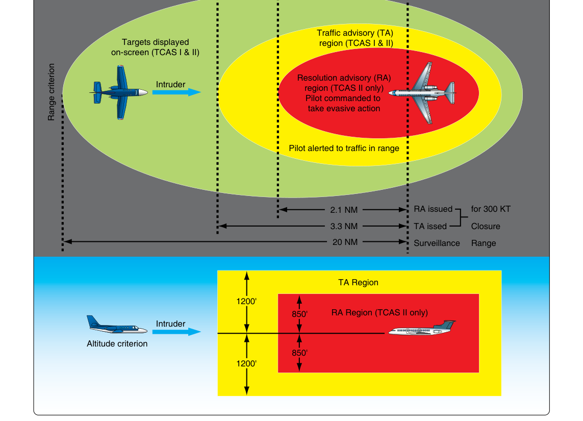
The Traffic Collision Avoidance System, universally known as TCAS II, is one of the most consequential pieces of safety equipment ever mandated for commercial air transport. Unlike passive warning systems that simply display traffic, TCAS II actively interrogates surrounding aircraft transponders, calculates collision threats, and — critically — issues coordinated resolution advisories (RAs) that direct both conflicting aircraft away from each other simultaneously. For an aviation maintenance technician working on airframes, a thorough understanding of TCAS II theory, its components, maintenance requirements, and limitations is essential both for the FAA knowledge test and for the shop floor.
TCAS II operates entirely independently of air traffic control. It does not rely on ATC radar, ATC communication, or any ground-based infrastructure to detect threats. This independence is its greatest strength in a high-density traffic environment and the reason the FAA and ICAO have mandated it on most turbine-powered transport category aircraft.
How TCAS II Works
At its core, TCAS II is an airborne interrogation system built around the same Mode C and Mode S transponder infrastructure already used by ATC. The host aircraft's TCAS II unit broadcasts interrogation signals on 1030 MHz. Nearby transponder-equipped aircraft reply on 1090 MHz. From the reply, TCAS II extracts altitude (Mode C or Mode S) and, with Mode S, a unique 24-bit aircraft address. By measuring the time between interrogation and reply, the system calculates slant range to the intruder.
The system uses a directional antenna array, typically mounted top and bottom on the fuselage, to determine the approximate bearing of the intruder. However, it is important to understand that TCAS II bearing accuracy is inherently less precise than range measurement. The system's threat logic depends far more heavily on range and closure rate than on bearing.
Tracking and Threat Evaluation
TCAS II continuously tracks all transponder-equipped aircraft within surveillance range — typically out to about 14 nautical miles horizontally and several thousand feet vertically — and builds a picture of each intruder's relative altitude and range over time. From this tracking data, the processor extracts two critical parameters:
- Range (and closure rate): How quickly the intruder is approaching, expressed in seconds to closest point of approach.
- Vertical separation and rate: The relative altitude and vertical speed of the intruder compared to the host aircraft.
The system then computes tau (τ) — the estimated time, in seconds, until the intruder reaches the host aircraft's position. Tau has two components: range tau (time to closest point of approach based on horizontal closure) and vertical tau (time until vertical separation reaches zero). Threat declarations are based on these computed times crossing defined thresholds that vary with altitude, because higher altitude typically means higher speed and greater closure rates.
Traffic Advisories and Resolution Advisories
TCAS II issues alerts in two escalating categories:
- Traffic Advisory (TA): Issued when an intruder is approaching but has not yet reached the RA threshold. The TA warns the flight crew to visually acquire the traffic. It does not direct any maneuver. Displayed on the cockpit display as a solid amber circle or equivalent symbology.
- Resolution Advisory (RA): Issued when the intruder crosses the RA threshold and a collision risk is imminent. The RA directs a specific vertical maneuver — climb, descend, maintain vertical speed, or reduce vertical speed. Displayed as a solid red square or equivalent symbology, and accompanied by an aural annunciation such as "CLIMB, CLIMB" or "DESCEND, DESCEND."
What makes TCAS II uniquely powerful is RA coordination via Mode S data link. When two TCAS II-equipped aircraft threaten each other, their units communicate directly, selecting complementary RAs so one aircraft climbs while the other descends. This coordination happens in milliseconds, without any human or ATC involvement. TCAS I, by contrast, provides only TAs and has no coordination or RA capability.
System Components
A complete TCAS II installation consists of several integrated components that the AMT must understand for inspection and maintenance:
- TCAS computer unit: The central processor that performs surveillance interrogations, threat evaluation, and RA computation. Often called the TCAS processor or ACAS computer.
- Mode S transponder: TCAS II requires a Mode S transponder (not just Mode A/C) to support the data-link coordination function. The transponder and TCAS processor may share antennas and circuitry.
- Directional antenna (top): A blade or phased-array antenna on the upper fuselage, used for interrogation and bearing determination of aircraft above.
- Omnidirectional antenna (bottom): Used primarily for aircraft below and for replies from non-directional transponders.
- Cockpit display unit (CDU) / Traffic Display: Shows intruder symbology and RA guidance, often integrated into the EFIS vertical speed indicator (VSI/TCD — Traffic and Collision Display) or the Navigation Display.
- Aural annunciator: Produces standardized voice commands such as "TRAFFIC, TRAFFIC," "CLIMB, CLIMB," "DESCEND, DESCEND," "INCREASE CLIMB," "MONITOR VERTICAL SPEED," and "CLEAR OF CONFLICT."
Why TCAS II Matters — Safety and Regulatory Context
Mid-air collisions at and around busy terminal areas were a significant safety concern through the 1970s and 1980s. TCAS II was developed in response to congressional mandate following several high-profile accidents. The FAA requires TCAS II on turbine-powered airplanes with more than 30 passenger seats or a maximum payload capacity greater than 7,500 pounds operating under 14 CFR Parts 121 and 135. ICAO standards (Annex 10 and Annex 2) require equivalent ACAS II (Airborne Collision Avoidance System II) equipage internationally.
From an airworthiness standpoint, TCAS II components are installed under a Supplemental Type Certificate (STC) or as original type design equipment. The system must be tested and verified to remain within TSO-C119 standards. TSO-C119 (versions b and c correspond to TCAS II versions 7.0 and 7.1) governs minimum performance standards for TCAS II.
TCAS II Version 7.1
The most current widely-deployed standard is TCAS II Version 7.1, which introduced the "crossing resolution advisory" inhibition logic. In Version 7.0, certain traffic geometries could produce RAs that directed one aircraft to cross through the other's altitude, which is counterintuitive to pilots. Version 7.1 logic avoids these crossing RAs, improving both safety and pilot compliance. AMTs should verify which software version is installed during maintenance checks, as Version 7.1 is required by FAA and EASA for international operations.
Maintenance Considerations for AMTs
TCAS II is a Line Replaceable Unit (LRU) system, meaning individual components — the TCAS processor, transponder, and antennas — are replaced rather than repaired in the field. Key maintenance tasks include:
- Antenna inspection: Directional arrays must be free of corrosion, delamination, and physical damage. Even minor damage to a phased-array antenna can degrade bearing computation accuracy.
- Functional testing: TCAS II requires periodic ground testing using FAA-approved TCAS test equipment and ramp test sets that simulate intruder transponders. The test must verify correct TA and RA annunciation and proper coordination logic.
- Transponder correlation: Because TCAS II and the Mode S transponder share operational logic, an avionics shop must ensure the two are compatible in firmware and properly configured.
- Wiring and connector integrity: The 1030/1090 MHz RF paths are sensitive to impedance mismatches. Coaxial cable condition, connector torque, and proper bonding are all maintenance checkpoints.
- Operational inhibits: TCAS II automatically inhibits certain RAs at low altitude to prevent nuisance advisories near the ground. Maintenance personnel must verify these altitude-based inhibit thresholds are functioning correctly per the manufacturer's Maintenance Manual.
Key Numbers and Rules
- Interrogation frequency: 1030 MHz (out) / 1090 MHz (reply)
- Surveillance range: approximately 14 NM horizontal
- Required equipage: turbine airplanes over 30 seats or with a maximum payload capacity greater than 7,500 lb (14 CFR Parts 121/135)
- TSO standard: TSO-C119b (Version 7.0) / TSO-C119c (Version 7.1)
- Transponder requirement: Mode S required for RA coordination
- TA display symbol: solid amber circle (filled)
- RA display symbol: solid red square (filled)
- Proximate traffic (non-threat): solid cyan/white diamond
- Pilot response to RA: immediate and in the correct direction — ATC cannot override a TCAS II RA
Common Test Traps
- TCAS I vs. TCAS II confusion: TCAS I provides only TAs — no RAs and no coordination. TCAS II provides both TAs and coordinated RAs. Exam questions often test this distinction directly.
- ATC authority vs. TCAS RA: When a TCAS II RA is issued, the pilot must comply with the RA even if it conflicts with an ATC clearance. The pilot notifies ATC afterward. Many students mistakenly believe ATC takes precedence.
- Transponder requirement: TCAS II requires the intruder aircraft to have an operating transponder. It cannot detect non-transponder traffic, including some gliders, ultralights, and military aircraft operating in certain modes.
- Bearing vs. range accuracy: Students sometimes assume TCAS II provides precise bearing. Range measurement (from reply timing) is precise; bearing from the directional antenna is approximate. The threat logic is range- and altitude-based, not primarily bearing-based.
- Version 7.1 crossing RA inhibition: Exam questions on TCAS II upgrades often focus on what Version 7.1 changed — specifically the elimination of crossing RAs — rather than general capability differences.