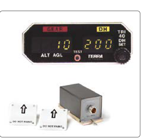
The radio altimeter — also called a radar altimeter or low-range radio altimeter (LRRA) — is one of the most safety-critical avionics systems on a transport-category or turbine-powered aircraft. Unlike a barometric altimeter, which measures atmospheric pressure and converts it to an altitude above a reference datum (usually sea level), the radio altimeter measures the actual geometric height of the aircraft above the terrain or water surface directly below it. This distinction is fundamental: a barometric altimeter does not know whether the ground below is at sea level or 8,000 feet; a radio altimeter always knows exactly how far the belly of the aircraft is from the surface it is flying over, making it indispensable during low-visibility instrument approaches, takeoff, and landing operations.
For the Aviation Maintenance Technician (AMT) working on airframe systems, a solid understanding of how the radio altimeter works, how it interfaces with other aircraft systems, and how to inspect and maintain it correctly is essential. Failures in this system can cascade into malfunctions of the Ground Proximity Warning System (GPWS), the Terrain Awareness and Warning System (TAWS), autoland autopilot modes, and decision-height alerting — all systems that directly protect flight crews during the most vulnerable phases of flight.
How the Radio Altimeter Works
The radio altimeter operates on the principle of frequency-modulated continuous wave (FM-CW) radar. The system continuously transmits a radio frequency signal — typically in the 4.2 to 4.4 GHz C-band range — downward from a transmit antenna mounted on the underside of the fuselage. A separate receive antenna, also mounted on the fuselage belly, captures the signal after it reflects off the terrain below. Because the system uses frequency modulation rather than pulsed timing alone, it can very precisely detect the difference between the frequency of the signal being transmitted at any instant and the frequency of the signal arriving back from the ground. This difference, called the beat frequency, is directly proportional to the round-trip travel time of the signal, and therefore to the height above the terrain.
The altitude is computed from the beat frequency using the basic relationship between the speed of light, round-trip distance, and the FM sweep rate. Because the speed of electromagnetic waves is constant, even very small height changes — measured in feet or even inches at extremely low altitudes — produce measurable and accurate changes in the beat frequency. This is why radio altimeters are highly accurate at low altitudes (typically certified to within a few feet below 500 feet AGL) but are generally only ranged to approximately 2,500 feet AGL on most transport-category systems; above that altitude, the barometric system is the primary altitude reference.
Antenna Configuration
The antenna installation is a critical maintenance consideration. Most systems use two separate blade-type antennas: one for transmit (TX) and one for receive (RX). These antennas must be mounted with a specific lateral separation — typically specified in the aircraft's Maintenance Manual — to prevent the transmitted signal from coupling directly into the receiver and overwhelming the much weaker ground-reflected return. The antennas must be oriented so that their beam patterns illuminate the ground directly below the aircraft, and the mounting surfaces must be flat and undistorted. Any dents, repairs, or sealant buildups around the antenna flanges that change the antenna tilt can introduce significant altitude errors at low heights.
System Components and Interfaces
A typical radio altimeter system consists of four main components: the radio altimeter transceiver (sometimes called the receiver-transmitter or RT), the transmit antenna, the receive antenna, and the radio altimeter indicator or signal output to the flight management and warning systems. On modern glass-cockpit aircraft, the indicator may be a dedicated round-dial instrument or a display element on the Primary Flight Display (PFD), showing height in feet from zero to the system's maximum range.
The radio altimeter output does not stay inside just the altimeter indicator. It is a shared, safety-critical data source fed to multiple other systems, including: the Ground Proximity Warning System (GPWS) or Enhanced GPWS/TAWS, which uses radio altitude to generate terrain warnings; the autopilot and flight director, which arm and execute autoland modes based on specific radio altitude thresholds (for example, flare initiation and thrust reduction commands); the decision height (DH) alerting system, which triggers an aural and visual alert when the aircraft descends through the crew-selected minimums; and the weather radar system on some aircraft, which uses radio altitude to manage beam tilt near the ground. A single faulty radio altimeter output can simultaneously disable all of these protections.
Why It Matters — Safety Relevance
The radio altimeter is one of relatively few avionics systems whose failure directly and immediately affects multiple, layered safety systems at the same time. During a Category II or Category III ILS approach — performed in near-zero visibility conditions — the radio altimeter is not merely advisory. It is the primary source of height information for the autoland system. If the radio altimeter reads erroneously high, the autopilot may flare too late, risking a hard touchdown. If it reads erroneously low, the aircraft may flare too early, causing a dangerously firm ground contact well short of the threshold or a sudden pitch-up followed by a stall. GPWS and TAWS warnings rely on radio altitude to determine when a terrain closure rate is truly dangerous versus normal during a stabilized approach; a faulty radio altimeter can cause spurious warnings or, critically, suppress valid warnings entirely.
For these reasons, many operators and aircraft manufacturers require a fully functional radio altimeter before dispatching an aircraft for low-visibility operations, and the Master Minimum Equipment List (MMEL) may prohibit flight under certain approach categories if the radio altimeter is inoperative. AMTs must be aware that signing off a radio altimeter discrepancy without proper return-to-service testing directly impacts approach minimums authorization.
Maintenance Practices and Inspection
Maintenance of the radio altimeter system falls into several key areas: antenna inspection, coaxial cable inspection, transceiver testing, and system functional testing.
Antenna inspection is performed at intervals specified in the aircraft's Maintenance Manual and at any time there is evidence of a bird strike, ground strike, or fuselage repair near the antenna locations. Inspect the antenna mounting flanges for cracks, corrosion, and proper torque on fasteners. Verify that the sealant around the antenna perimeter is intact and that no gaps exist that could allow moisture intrusion into the fuselage structure. Check that the antenna face is not chipped, cracked, or coated with non-approved materials that could attenuate the radar signal.
Coaxial cable and connector inspection is critical. The cables connecting the transceiver to the transmit and receive antennas are impedance-controlled, typically 50-ohm coaxial lines. Even a slightly damaged connector, a kinked cable, or improper installation of a connector can introduce signal reflections that corrupt the beat frequency measurement and cause altitude errors or system failure flags. Inspect cables for chafing, sharp bends, pinching by other components, and moisture in connectors. Use a Time-Domain Reflectometer (TDR) or the method specified in the maintenance manual to check cable integrity when a fault is suspected.
Transceiver testing is typically accomplished using an approved radio altimeter test set, which simulates a ground reflection at a known distance and verifies that the system indicates the correct altitude. Some test sets can simulate multiple altitude values to verify accuracy across the operating range. Always follow the aircraft maintenance manual procedures exactly — unauthorized substitution of test equipment can damage the transceiver or produce misleading results.
System functional testing after any antenna replacement, cable repair, or transceiver replacement should verify that the radio altimeter indication correctly drives all downstream systems: confirm that the GPWS/TAWS receives the altitude data, that the decision-height alert functions at the correct altitude, and that the autopilot autoland arming and mode sequences properly during a simulated approach. This often requires coordination with avionics personnel and may require a ground check as described in the aircraft's Airplane Flight Manual (AFM) or Operations Manual.
Key Numbers and Rules
- Operating frequency: Typically 4.2–4.4 GHz (C-band); this protected aviation band is reserved specifically for radio altimeters.
- Typical operating range: 0 to approximately 2,500 feet AGL for transport-category systems; accuracy is highest below 500 feet AGL.
- Antenna separation: Specified in the aircraft Maintenance Manual — improper separation causes direct coupling and system failure or errors.
- Coaxial cable impedance: Typically 50 ohms; mismatched or damaged cables degrade signal integrity.
- Cat II/III dependency: Most operators cannot legally conduct Cat II or Cat III autoland approaches with an inoperative or degraded radio altimeter — verify MMEL status before return to service.
- Interference sensitivity: The 4.2–4.4 GHz band is protected, but operations near 5G cellular installations have been a subject of FAA airworthiness concern; refer to current FAA airworthiness directives and Special Airworthiness Information Bulletins for current guidance.
Common Test Traps
- Confusing radio altitude with barometric altitude: Radio altimeters measure height above terrain (AGL), not above mean sea level. They are unaffected by altimeter settings (QNH) or nonstandard atmospheric pressure.
- Assuming the radio altimeter only feeds the indicator: The radio altimeter output drives GPWS/TAWS, autopilot, decision-height alerting, and sometimes weather radar — a single failure has multiple downstream consequences.
- Antenna substitution without checking beam pattern: Not all blade antennas with the same connector are interchangeable. Always verify part number and antenna orientation comply with the Maintenance Manual.
- Overlooking coaxial cable integrity: Many radio altimeter squawks that initially point to the transceiver are ultimately traced to a damaged connector or kinked coaxial cable between the transceiver and the antenna.
- Skipping full system functional test after repair: Replacing a single component (antenna, cable, or transceiver) and verifying only the altitude indicator is insufficient. The entire signal chain and all downstream system interfaces must be verified before return to service.