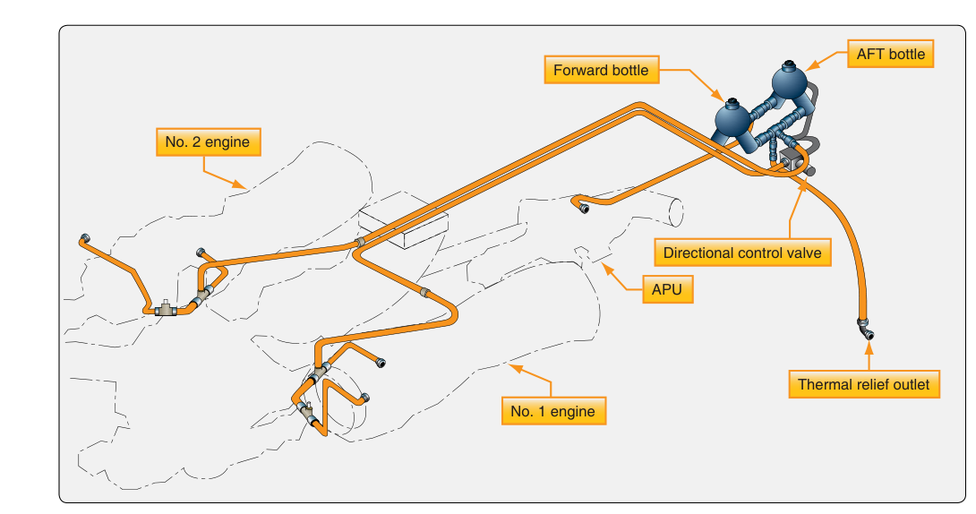
Engine fires represent one of the most serious hazards in aviation, and aircraft designers have long recognized that a reliable, fast-acting suppression system is essential for protecting powerplants and their surrounding structure. The two-shot fire extinguishing system is the standard design found on most turbine-powered transport-category aircraft and many turboprop regional airliners. As the name implies, it provides two separate discharges of extinguishing agent — two opportunities to knock down a fire before the crew considers other emergency actions. For the AMT powerplant technician, a thorough understanding of this system's components, operational logic, squib function, and maintenance requirements is both a certification exam topic and a critical safety responsibility.
This article covers the system from first principles: why two shots are used, how the hardware is arranged, what a squib actually does and how it is tested, and what the technician must watch for during inspection and servicing.
Why Two Shots?
A single container of extinguishing agent might extinguish a fire on the first discharge, but there is always the possibility that the fire re-ignites — perhaps because a fuel leak continues, hot metal re-radiates heat, or the first discharge was only partially effective. Providing a second, independent charge gives the flight crew a backup capability without requiring the aircraft to carry an entirely separate, duplicate system for each engine. The two-shot philosophy balances weight, cost, and safety: both shots are aimed at the same fire zone, but each shot comes from its own container through its own discharge valve, so a failure in one circuit does not disable the other.
On most designs, the two containers are cross-connected across engines — that is, either bottle can be directed to either engine nacelle. This cross-feed arrangement means that if one engine has already used both of its assigned shots, or if one container fails to discharge, agent from the other engine's bottles can still be routed to the affected nacelle. This dramatically increases system redundancy without adding extra hardware.
System Components and Layout
The core hardware of a two-shot fixed fire extinguishing system consists of the following elements working together:
- Agent containers (bottles): High-pressure spherical or cylindrical steel or titanium vessels charged with a halogenated extinguishing agent — historically Halon 1301 (bromotrifluoromethane) on older aircraft, and newer environmentally compliant agents such as HFC-227ea (heptafluoropropane) on more recent designs. Each container is pressurized, typically with dry nitrogen as a super-pressurizing gas to ensure rapid, complete expulsion of the agent. Container pressure and agent quantity are verified during preflight and scheduled inspections.
- Discharge valves (squib-operated): Each container outlet is sealed by a frangible disk or a piston assembly that is ruptured or driven open by an explosive squib (also called a cartridge or initiator). These valves are normally closed and remain leak-proof under full container pressure until electrically fired.
- Squibs: Small pyrotechnic devices threaded into the discharge valve head. When electrical current is applied, a bridge wire inside the squib heats and ignites a charge, producing a sharp pressure pulse that ruptures the frangible disk or drives the valve piston, releasing the agent. Squibs are one-shot devices — once fired they must be replaced.
- Distribution tubing and nozzles: Stainless steel or titanium tubing routes agent from the container outlet to spray nozzles positioned inside the protected fire zone (the engine nacelle, tailpipe area, or dry bay). Nozzles are sized and aimed to distribute agent uniformly throughout the zone.
- Check valves: Installed in the distribution lines to prevent backflow and to ensure that when cross-feed is used, agent flows only toward the intended nacelle and not backward into the other engine's zone.
- Cockpit controls and indicators: Guarded fire handles or pushbuttons allow the crew to arm and fire each shot. Indicator lights or extinguisher discharge lights illuminate to confirm that a squib has fired and agent has been released.
Squib Operation in Detail
The squib is the critical enabling component — it is the electrical-to-mechanical conversion device that actually opens the system. Understanding its operation helps the technician appreciate both the reliability requirements and the maintenance restrictions surrounding it.
A squib consists of a bridge wire — an extremely fine resistance wire — embedded in a heat-sensitive pyrotechnic compound, all housed in a robust threaded metal body. When a DC electrical current (typically specified by the aircraft manufacturer, commonly in the range of 1 to 5 amperes depending on design) flows through the bridge wire, resistive heating ignites the pyrotechnic charge within milliseconds. The resulting hot gas pulse is contained and directed against the frangible disk or piston of the discharge valve, opening it in a fraction of a second.
Because squibs are electro-explosive devices (EEDs), they demand strict handling precautions. Static electricity, stray radio frequency (RF) energy, or inadvertent application of electrical power can fire a squib unexpectedly, releasing the extinguishing agent and potentially injuring personnel. Key handling rules include:
- Always install the shorting plug (safety pin or shunt plug) on a squib's electrical connector whenever the squib is out of the aircraft or not connected to the aircraft's wiring. The shorting plug ties both lead wires together, preventing static buildup from reaching the bridge wire.
- Keep squibs away from transmitting antennas and RF sources while uninstalled.
- Follow the manufacturer's resistance specification when ohm-testing a squib — apply only the specified low-level test current. Using a standard ohmmeter that delivers excessive current can fire the squib or degrade it.
- Squibs have a shelf life and a service life stamped on their packaging. Never install an expired squib.
After the system fires — either in an actual emergency or during a ground discharge test — all expended squibs must be replaced, the containers must be recharged or replaced (depending on design), and the distribution lines must be inspected for agent residue, corrosion, or damage before return to service.
Container Pressure and Agent Quantity Checks
Most containers are equipped with a pressure gauge or a pressure indicator disk accessible from outside the nacelle. The gauge reading must fall within the manufacturer's specified band for the ambient temperature, since agent pressure varies with temperature. Some aircraft use a red blow-out disk (thermal discharge indicator) on the container. If this disk is missing or shows signs of discharge, the container has released its agent thermally (due to overpressure from heat) and must be replaced. A yellow disk at the drain fitting indicates the first shot has been fired; a second yellow indicator covers the second shot. Technicians must always compare the number of indicators blown against the cockpit fire system status before signing off an inspection.
Cross-Feed and Selector Valve Logic
On twin-engine aircraft, a typical arrangement places one container in each nacelle. The left engine's first shot uses its own container; the left engine's second shot draws from the right engine's container (and vice versa). A selector valve or a network of check valves routes the agent appropriately based on which squib circuit the crew activates. In some designs, a motor-operated selector valve must first move to the cross-feed position before the second shot can be directed to the opposite nacelle. The technician must understand the logic for that specific aircraft to test and verify system integrity correctly.
Key Numbers and Rules
- Two-shot systems provide two independent agent discharges to the same fire zone; both shots must be available for airworthiness.
- Squibs are one-time-use pyrotechnic devices and must be replaced after any firing, accidental or intentional.
- Container pressure must be checked against the manufacturer's temperature-pressure chart — a gauge reading alone without a temperature correction is insufficient.
- Halon 1301 was the historical agent of choice but is now controlled under international environmental agreements; replacement agents such as HFC-227ea are approved and in common use.
- Squib resistance testing must use a manufacturer-approved low-current ohmmeter — standard ohmmeters may deliver enough current to fire the device.
- A missing or ruptured red thermal discharge disk on a container means the agent has been expelled and the container must be replaced before flight.
- 14 CFR Part 25 requires that transport-category aircraft engine fire extinguishing systems be capable of extinguishing a fire and providing a sufficient concentration of agent to prevent re-ignition.
Common Test Traps
- Confusing the number of shots with the number of containers: A two-shot system has two containers, but on cross-connected systems those containers may serve either engine — the system doesn't give each engine two dedicated bottles simultaneously.
- Testing a squib with a standard ohmmeter: The FAA exam frequently tests whether the technician knows to use only a squib-safe ohmmeter (also called a low-power ohmmeter or EED tester) — standard shop ohmmeters can deliver enough bridge-wire current to initiate the squib.
- Overlooking the shorting plug: Removing the squib's connector without first installing the shorting plug is a major safety error and is a common distractor on AMT written questions about squib handling.
- Interpreting a pressure gauge alone as airworthy: Agent pressure must be cross-checked against ambient temperature using the manufacturer's chart. A bottle that reads in the green at 0°C may be under-charged at 40°C, or vice versa.
- Assuming Halon 1301 is still the required agent: Many questions reference Halon because it appears throughout older handbooks, but current regulatory and environmental requirements have shifted to approved replacement agents on new installations. Know that Halon is restricted, not that it is universally approved.