Aircraft fire detection systems are among the most safety-critical circuits on any powerplant installation. When a detector activates, the crew must trust that signal completely — yet the system must never cry wolf with nuisance alarms. For the Aviation Maintenance Technician (AMT) seeking a Powerplant certificate, understanding how to test, verify, and fault-isolate these circuits is both an FAA written-exam staple and a real-world shop skill. This article covers the types of detection systems in common use, the standardized test procedures the FAA recognizes, and a methodical approach to isolating the most common circuit faults.
Fire detection is not a single device but a system: sensors, wiring loops, control units, cockpit annunciators, and sometimes extinguisher squib circuits all form an integrated chain. A fault anywhere in that chain can produce two equally dangerous failure modes — a missed fire warning, or a false alarm that causes a crew to shut down a perfectly healthy engine. The AMT's job is to find and eliminate both.
Types of Fire Detection Elements and Their Test Points
The FAA Powerplant handbook describes several detector designs, each with its own test approach:
- Thermocouple systems sense the rate of temperature rise, not absolute temperature. A thermocouple detector will not activate in a slow heat-soak situation, only during rapid temperature increase. Thermocouple fire-detection circuits are typically tested using a test relay/test switch that simulates the electrical signal produced by a hot thermocouple relative to the average (reference) thermocouples in the circuit, rather than by applying a heat gun directly to the sensing elements in the field. This test verifies that the averaging-thermocouple arrangement correctly discriminates a genuine rate-of-rise event from slow ambient temperature changes, preventing nuisance alarms.
- Thermal switch (spot detector) systems use bimetallic or fusible-plug switches that close at a set temperature. These switches are wired in parallel so any one switch closing completes the alarm circuit. Testing involves applying localized heat to individual switches with a heat gun while monitoring cockpit indication. The wiring loop itself is continuity-checked with an ohmmeter.
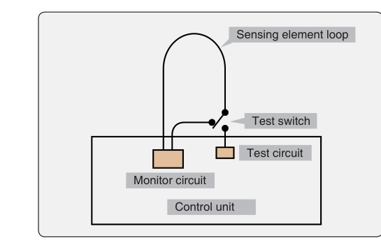
- Continuous-loop systems (Kidde and Fenwal types) use a sealed metal tube containing a core material that changes electrical characteristics with temperature. Kidde-type loops use a thermistor-type core whose resistance decreases as temperature rises, providing a continuous, averaging response along the loop. Fenwal-type loops use a eutectic-salt core that undergoes a sharp, discrete drop in resistance at a specific temperature, producing more of a discontinuous, threshold-type response rather than a continuously averaged one. These systems are the most prevalent on turbine powerplants. Each loop has a test switch in the cockpit that routes a resistance signal through the control unit to simulate a detection event without actually heating the element.
- Pneumatic/gas-pressure systems (Systron-Donner type) use a sealed tube containing a gas core that increases pressure with temperature. A responder at the end of the tube converts pressure change into an electrical signal. Testing this type involves verifying that the pneumatic integrity of the tube is intact and that the responder diaphragm is functional.
The Standard Test Procedure for Continuous-Loop Systems
Because continuous-loop detectors are dominant on modern turboprops and jets, AMT candidates must understand their test procedure in detail. The FAA guidance and manufacturer maintenance manuals align on a structured sequence:
- Cockpit test-switch check. With aircraft power applied and the engine cold, the pilot or technician presses the fire-detector test switch. This energizes a test relay inside the control unit that simulates the resistance change of a hot loop. The fire warning light and bell must activate within the manufacturer's specified response time for that installation. Failure to alarm indicates a fault in the control unit, the annunciator circuit, or the test relay itself — not necessarily the sensing loop.
- Loop resistance check. Using a calibrated ohmmeter, the technician measures resistance across the sensing loop with connectors disconnected from the control unit. The reading must fall within the manufacturer's resistance tolerance at the ambient temperature at the time of the test. Because thermistor-type sensing element resistance is temperature-dependent, a Temperature Resistance Chart supplied in the maintenance manual must be consulted. An out-of-tolerance reading points to a degraded sensing element or a chafed harness fault.
- Insulation resistance check. A megohmmeter (Megger) is used to verify that the sensing loop is properly insulated from the aircraft structure. The FAA handbook emphasizes that the loop must meet the minimum insulation resistance value specified by the manufacturer for that particular system between the inner conductor and the outer tube (ground) — this value varies by installation and must be confirmed in the applicable maintenance manual. A low insulation resistance value is the most common cause of false-alarm faults and is almost always the result of moisture intrusion, damaged loop sections, or contamination.
- Continuity of the complete circuit. With the sensing loop reconnected, a continuity check confirms that the full circuit from the control unit through all connectors to the loop and back is unbroken. This catches open-circuit faults that would prevent a real fire from ever generating an alarm.
Why Fault Isolation Matters — Safety and Airworthiness
An intermittent false alarm is not a nuisance to be tolerated — it is an airworthiness defect. Crews who experience repeated false alarms can become desensitized, a classic example of the hazard the FAA Risk Management Handbook calls complacency. On multi-engine aircraft, an erroneous fire warning can also lead to an unnecessary in-flight engine shutdown, loss of thrust, and potential hazard to the flight.
Conversely, a latent open-circuit fault means the crew would receive no warning during an actual fire — perhaps the most catastrophic failure mode imaginable. Title 14 CFR Part 25 (25.1203, for transport category aircraft) establishes airworthiness standards for fire detection systems generally, and system safety analysis and design practice — rather than a single codified numeric requirement — is why modern control units often include a fault annunciator distinct from the fire annunciator to alert the crew to loop faults. Part 23 and Part 33 requirements similarly mandate reliable detection. AMTs working under Part 145 repair station authority or performing line maintenance must document all test results and any corrective action on FAA Form 337 or in the aircraft logbook as appropriate.
Fault Isolation: Step-by-Step Logic
When a ground test reveals a discrepancy, systematic isolation prevents misdiagnosis and unnecessary parts replacement. The general sequence follows a divide-and-conquer strategy:
- False alarm / unwanted activation: Start by disconnecting the sensing loop at the control unit. If the alarm clears, the fault is in the loop or its harness — proceed to the insulation resistance check. If the alarm persists with the loop disconnected, the control unit or annunciator wiring is the source.
- No alarm on test / open circuit: Disconnect the loop at the control unit. Using a jumper wire, short the loop terminals together at the control-unit connector. If the alarm now activates, the loop element or its harness has an open circuit. Systematically disconnect the loop at each junction connector to isolate the open to a specific section.
- Intermittent alarm: Intermittent faults are the most difficult to isolate. The most productive first step is a careful visual inspection of the entire loop routing for chafing against structure, clamp damage, heat-damaged sections near hot-section panels, or corroded connectors. Wiggling individual harness sections while monitoring the cockpit annunciator often reproduces the fault. A moisture-contaminated connector will frequently show normal insulation resistance when dry and low resistance when exposed to water or condensation — so test conditions matter.
- Isolating a specific loop section: Many installations use multi-section loops (A loop and B loop, or multiple zones). By isolating each section with a process of elimination — disconnecting one section at a time and re-testing — the technician can narrow the fault to the smallest replaceable unit without removing the entire loop.
Key Numbers and Rules
- Insulation resistance must meet or exceed the minimum value specified by the manufacturer for the specific system installed; always verify the exact value in the applicable maintenance manual rather than assuming a single universal figure.
- Loop resistance tolerance is temperature-dependent — the correct value must be read from the manufacturer's temperature-resistance chart at the measured ambient temperature.
- Test-switch response time requirements are manufacturer-specified and vary by installation; always confirm the applicable response-time limit in the maintenance manual rather than assuming a fixed value across all turbine aircraft.
- Continuous-loop elements must be visually inspected for kinks, dents, or cracked outer jackets per the specific damage limits published in the applicable maintenance manual — mechanical damage almost always causes either shorts or opens.
- After any repair or replacement, a complete functional test (test-switch plus resistance checks) must be performed before return to service.
- All fire detection maintenance must be recorded per 14 CFR Part 43 requirements.
Common Test Traps
- Confusing thermocouple and thermal switch logic: The FAA written exam distinguishes these sharply. Thermocouple systems respond to rate of temperature rise — they will NOT alarm during a slow heat soak. Thermal switch systems respond to absolute temperature and will alarm regardless of rate.
- Assuming the test switch tests the entire loop: The cockpit test switch typically tests the control unit and the annunciator circuit, not the sensing loop itself. A loop with an open circuit can still pass the test-switch check because the test current bypasses the loop internally.
- Ignoring ambient temperature for resistance checks: A loop resistance reading that looks out of tolerance may be perfectly correct once the temperature-resistance chart is consulted. Failing to account for ambient temperature leads to unnecessary loop replacements.
- Treating a false alarm as an intermittent nuisance: Any unscheduled fire warning on the ground requires a full fault-isolation procedure before return to service — it cannot be dismissed as a glitch.
- Forgetting insulation resistance testing after mechanical repairs: Reinstalling a repaired loop section without performing a Megger check is a common maintenance error. Chafing or poor connector seating not visible to the eye is caught only by the insulation resistance test.