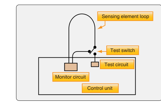
Fire protection in aircraft powerplants is one of the most critical safety systems an Aviation Maintenance Technician (AMT) must understand. Among the most widely used detection technologies are the Kidde and Fenwal continuous loop systems. Unlike single-point fire detectors, continuous loop systems provide complete, zone-wide coverage along every inch of a sensing element routed through the engine nacelle, wheel wells, and other fire zones. This means a fire or dangerous overheat condition anywhere along the loop will trigger an alarm — a significant advantage in large, complex engine compartments where a localized detector might miss a fire that develops in an unexpected location.
This article covers the operating principles, construction, differences between Kidde and Fenwal designs, system testing, and maintenance considerations as grounded in FAA guidance. Understanding these systems is essential both for the AMT Powerplant knowledge test and for practical airworthiness work.
What Is a Continuous Loop System?
A continuous loop fire detector is a long, flexible sensing element — essentially a specialized wire or tube — that is routed throughout a designated fire zone. The element is connected at both ends (or at one end with the other terminated) to a control unit that monitors its electrical characteristics. When temperature rises to the alarm threshold anywhere along the loop, the system signals the cockpit. Because detection is distributed evenly along the entire length of the element, there are no blind spots. The two dominant designs used in certificated aircraft are the Kidde (also called the Systron-Donner or Guardian) system and the Fenwal system, each using different physical principles to achieve the same protective goal.
How the Kidde Continuous Loop System Works
The Kidde system uses a sensing element constructed from a small-diameter, stainless steel outer tube filled with a eutectic salt or thermistor-type material that has a sharply decreasing electrical resistance as temperature rises. At the core of the tube runs an inner conductor (a single wire), separated from the outer tube by the thermistor-type material. Under normal (cool) conditions, the core material acts as an insulator — resistance between the center wire and the outer tube is very high, so very little current flows. As temperature increases toward the alarm threshold, the resistance of the core material drops dramatically, allowing measurable current to flow between the center conductor and the outer tube (which serves as the ground return). The control unit continuously monitors this resistance. When resistance falls below a preset value — corresponding to the alarm temperature — the control unit activates the fire warning circuit.
A key feature of the Kidde system is that it is a two-wire system in many configurations. One version uses a single center conductor and the outer sheath as the second conductor. More sophisticated versions use two center conductors embedded in the thermistor material, which allows the system to differentiate between a real fire signal and a short circuit caused by mechanical damage. If only one conductor reads low resistance, it indicates a system fault rather than a fire; a genuine fire causes both conductors to show low resistance simultaneously. This fault-detection capability prevents false alarms from wiring damage and is an important maintenance consideration.
The element can be fabricated in virtually any length and routed with bends and clamps throughout the nacelle. It is self-restoring: once the overheat condition is removed and the element cools, its resistance returns to normal and the alarm clears. This reset capability without replacing any components is a major operational advantage.
How the Fenwal Continuous Loop System Works
The Fenwal system operates on a related but distinct principle. Its sensing element is also a flexible, stainless steel tube, but instead of a thermistor-based compound, the tube is filled with a discrete quantity of inert gas and a core of eutectic salt. Inside the tube, the eutectic salt surrounds a single center conductor and remains in a solid, electrically resistive state at normal temperatures, acting as an insulator just as in the Kidde system.
The critical difference is that the Fenwal element responds to both average temperature rise and discrete high temperature. When the average temperature along the entire loop rises significantly — indicating a widespread overheat condition such as a bleed air duct leak — the inert gas inside the tube expands, increasing internal pressure. This pressure increase can be used to actuate a pressure switch for alarm. Simultaneously, if any localized point along the loop reaches the eutectic salt's melting point, the salt liquefies at that spot, its resistance drops sharply, current flows between the center conductor and the outer sheath, and the control unit triggers the alarm. The Fenwal system therefore provides dual-mode detection: it responds to both slow, widespread temperature increases and fast, localized fires.
Like the Kidde system, the Fenwal element is self-resetting after a localized alarm, provided the eutectic salt re-solidifies upon cooling and the element was not physically damaged. This makes post-flight inspection especially important — if an alarm cleared on its own, the element must still be inspected for damage and the system must be tested before return to service.
Control Units and Alarm Logic
Both systems connect their sensing elements to an electronic control unit (sometimes called a fire detection control unit or sensing loop controller). The control unit supplies a small, regulated voltage to the sensing element and monitors the resulting current or resistance. It incorporates alarm and fault logic that distinguishes between:
- Normal condition: High resistance across the loop, no alarm.
- Fire or overheat condition: Resistance drops uniformly or at a specific point, triggering the fire warning light and bell in the cockpit.
- Loop fault (open circuit): Resistance reads infinitely high — the circuit is broken — indicating a broken element or disconnected connector. A fault warning (distinct from a fire warning) annunciates.
- Loop fault (short circuit): In single-conductor Kidde systems, a short may be indistinguishable from a fire; in dual-conductor versions, the logic separates fault from fire. This is why the dual-conductor design is preferred on transport-category aircraft.
Most large aircraft use dual-loop systems, with two independent sensing elements routed through the same fire zone. Either loop can independently generate a fire warning, so the loss or fault of one loop does not eliminate fire detection capability in that zone — the system provides redundancy rather than requiring agreement between loops.
Routing, Support, and Maintenance
Proper installation is just as important as the sensing element's design. The FAA's guidance (reflected in AC and manufacturer maintenance manuals) requires that sensing elements be supported with clamps at intervals specified by the manufacturer — typically every eight to ten inches or as specified — to prevent chafing, vibration fatigue, and kinking. Elements must not contact hot engine surfaces directly, must have adequate bend radius, and must be protected from mechanical damage in exposed areas. Areas where the element passes through bulkheads or firewalls require protective grommets.
Continuity and integrity testing is performed using the aircraft's built-in test equipment (BITE) or by applying a test signal at the control unit. Technicians should verify that the fire warning triggers when the system is tested and that the fault circuit functions when a loop is intentionally opened. After any maintenance on the engine or nacelle that required disturbing the sensing element, a full operational test is mandatory before return to service.
Key Numbers and Rules
- Alarm threshold: Varies by aircraft and zone, but is typically set between approximately 400°F and 1,000°F (roughly 204°C to 538°C) depending on the fire zone and system design. Consult the specific aircraft maintenance manual for exact values.
- Support spacing: Sensing elements must be clamped at intervals per the manufacturer's data — commonly every 8–10 inches in vibration-prone areas.
- Dual-loop logic: On dual-loop systems, either loop alone can generate a fire warning; this redundancy ensures a damaged or failed loop does not eliminate fire detection in that zone.
- Self-resetting: Both Kidde and Fenwal elements reset automatically when cooled, but a post-alarm inspection is still required before the aircraft is returned to service.
- Open circuit fault: An open loop (infinite resistance) indicates a broken or disconnected element — a maintenance fault, not a fire condition.
- Short circuit: In single-conductor systems, a short mimics a fire; dual-conductor Kidde systems can distinguish between the two conditions.
Common Test Traps
- Confusing Kidde and Fenwal principles: The Kidde system relies primarily on decreasing electrical resistance of a thermistor core material; the Fenwal system uses a eutectic salt that melts to reduce resistance AND uses gas pressure for average overheat detection. Know that both sense changes in electrical resistance but achieve it differently.
- Assuming a cleared alarm means no problem: Both systems are self-resetting, which can mislead technicians into thinking a transient alarm requires no follow-up. FAA guidance is clear: any fire warning must be investigated and the system tested before the aircraft returns to service.
- Misidentifying an open-circuit fault as normal: An open loop does NOT mean no fire — it means the fire detection capability for that zone is lost. A fault warning must never be ignored.
- Forgetting dual-loop alarm logic: On dual-loop installations, either loop alone can generate a valid fire warning — this is precisely why dual loops are installed, so damage to one loop does not disable fire detection. Test questions often probe this redundancy concept.
- Ignoring element support requirements: A common maintenance error is leaving the sensing element unsupported after work in the nacelle. Vibration-induced chafing is a leading cause of nuisance alarms and element failure — always re-clamp per manufacturer specifications.