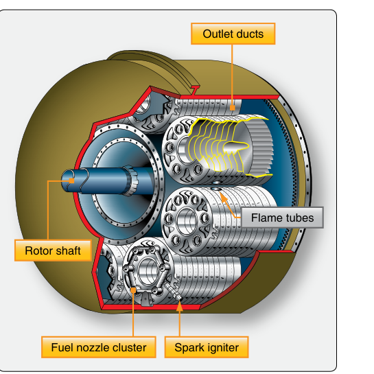
When you trace the path of air through a gas turbine engine — from the intake fan through the compressor stages and finally out the turbine and exhaust — the combustion chamber sits at the heart of the process. It is where chemical energy locked inside aviation fuel is released as heat, dramatically expanding the gas before it drives the turbine. Of the three main combustion chamber designs recognized in FAA powerplant curriculum — can-type, can-annular (cannular), and annular — the annular combustion chamber has become the dominant choice for modern turbofan and turbojet engines. Understanding its construction, airflow mechanics, and operational characteristics is essential for any AMT Powerplant candidate.
This article walks through how an annular combustion chamber is built, how air and fuel behave inside it, why engine designers prefer it, and the critical inspection and operational details you need to know for the FAA Powerplant knowledge test and practical work on the shop floor.
Basic Design and Construction
An annular combustion chamber consists of a single, continuous, ring-shaped (annular) combustion liner enclosed within an outer housing and an inner housing that together form a concentric assembly surrounding the engine's main shaft. Unlike can-type chambers, which use multiple individual cylindrical cans, and can-annular chambers, which use multiple cans arranged inside a shared annular housing, the annular design uses one uninterrupted combustion space that wraps completely around the engine core.
The main structural components include:
- Outer combustion case: The outermost structural shell, usually made from sheet steel or a nickel alloy, that contains internal pressure and supports the liner.
- Inner combustion case: A smaller concentric housing closer to the engine shaft that, together with the outer case, forms the annular passage.
- Combustion liner (flame tube): The perforated inner wall that defines the actual combustion zone. It is typically fabricated from high-temperature nickel or cobalt alloys. The liner must withstand extreme thermal cycling and direct flame contact.
- Fuel nozzles (fuel injectors): Multiple fuel nozzles are spaced evenly around the annular liner to introduce atomized fuel into the airstream. Modern engines use simplex, duplex, or airblast nozzles depending on the design.
- Igniter plugs: Commonly, two igniter plugs are installed at specific positions around the annular liner for starting, though this is a typical industry configuration rather than a fixed handbook requirement. Because the chamber is continuous, the flame propagates circumferentially around the ring once ignition is achieved — the remaining nozzles do not each require their own igniter.
The liner itself is not a solid wall. It is carefully perforated with primary air holes, dilution air holes, and cooling louvers or film-cooling slots, each positioned precisely to control the internal airflow pattern and temperature distribution. Modern liners may also incorporate effusion cooling, where thousands of tiny holes allow a thin film of cooler air to flow along the liner's inner surface, protecting the metal from the flame.
Airflow and Combustion Operation
Understanding how air is divided inside an annular chamber is central to both the FAA test and real-world troubleshooting. Not all air that enters the combustion section participates directly in burning fuel. In fact, only a fraction of the total airflow — commonly cited as roughly 20 to 30 percent — enters the primary combustion zone and mixes with fuel to sustain combustion. The remaining air serves cooling and dilution functions. This division is sometimes described in three zones:
- Primary zone: Air enters through the primary holes in the forward section of the liner and mixes with atomized fuel introduced by the fuel nozzles. This zone is intentionally fuel-rich to sustain a stable flame. Swirl vanes on the fuel nozzles or liner geometry promote recirculation — a toroidal vortex that anchors the flame and prevents it from blowing out.
- Intermediate (secondary) zone: Additional air is admitted through holes farther aft on the liner to complete combustion of any unburned hydrocarbons and to begin cooling the hot gas stream. This zone brings combustion toward completion and reduces carbon monoxide and unburned fuel emissions.
- Dilution zone: Large dilution holes near the aft end of the liner admit significant quantities of relatively cool compressor air. This air mixes with the combustion products to lower the average gas temperature to a level that the turbine nozzle guide vanes and first turbine stage can safely tolerate. Without proper dilution, turbine inlet temperature (TIT) would destroy the turbine in seconds.
The resulting temperature profile across the exit plane of the combustion chamber is called the temperature traverse or radial temperature distribution. Designers work to achieve an even distribution so that no single area of the first turbine stage receives a hot streak that would cause accelerated oxidation and fatigue.
Advantages Over Other Combustion Chamber Designs
The annular design offers several significant advantages that explain its prevalence in modern engines:
- Compact length and lower weight: Because combustion occurs in a single continuous ring rather than in multiple individual cans, the annular chamber can be made shorter and lighter for the same power output. This directly reduces overall engine length and weight — critical for airframe integration.
- Lower pressure drop: The large unobstructed annular flow area reduces the total pressure loss across the combustion section compared to can or can-annular designs, improving overall engine thermal efficiency.
- More uniform exit temperature: With properly spaced fuel nozzles distributed evenly around the full circumference, an annular chamber can achieve a more uniform temperature profile at the turbine entrance, extending turbine component life.
- Reduced combustion surface area-to-volume ratio: The annular geometry provides more combustion volume relative to the cooled liner surface area, which improves combustion efficiency and reduces heat rejection to the liner walls.
The primary disadvantage of the annular design is that the liner is physically more difficult to remove for inspection and repair. On can-annular systems, individual cans can often be removed without full engine teardown. On a fully annular chamber, significant disassembly is typically required to access the liner, which increases maintenance time and cost.
Inspection and Maintenance Considerations
From an AMT perspective, the combustion liner is one of the most critical inspection items at any hot-section inspection. Inspectors look for:
- Cracks: Thermal fatigue causes cracks to initiate at stress concentrations around holes, louvers, and repaired areas. Any crack must be evaluated against the engine manufacturer's serviceable limits — many cracks are cause for removal and repair or replacement.
- Buckling and warping: Overtemperature events can cause the liner to distort, disrupting the designed airflow pattern and leading to hot spots on the turbine.
- Erosion and burning: Locally rich combustion caused by a malfunctioning fuel nozzle can burn through the liner wall. Fuel nozzle condition is therefore a direct predictor of liner condition.
- Carbon deposits: Incomplete combustion from poor fuel atomization or improper airflow can deposit carbon on liner surfaces and nozzle tips, partially blocking cooling holes and accelerating localized overheating.
Fuel nozzles must be inspected, flow-checked, and cleaned on the intervals specified by the engine manufacturer. A nozzle that delivers a poor spray pattern or excessive flow deviation creates uneven temperature distribution in the combustion zone.
Key Numbers and Rules
- Annular chambers commonly use two igniter plugs as a typical industry configuration, relying on circumferential flame propagation to light all fuel nozzles.
- Approximately 20–30% of total airflow participates in the primary combustion reaction; the remainder provides cooling and dilution.
- Stoichiometric combustion of Jet-A fuel occurs at an air-to-fuel ratio of approximately 15:1 by weight; the overall engine air-to-fuel ratio is much higher (often 30:1 to 60:1 depending on power setting) because of the large dilution airflow.
- Turbine inlet temperatures in modern high-performance engines can reach into the 2,000 °F (1,090 °C) range and above, well beyond the melting point of even the best turbine alloys — making combustor exit temperature control and turbine cooling essential.
- A well-designed annular chamber achieves high combustion efficiency at design operating conditions, though exact figures vary by engine model and should be referenced from the specific manufacturer's data.
Common Test Traps
- Confusing can-annular with annular: Can-annular (cannular) chambers use multiple individual liners inside a shared annular housing. True annular chambers have one continuous liner. The FAA test exploits this distinction directly — read each question carefully.
- Assuming all air is burned: Many students incorrectly think all compressor discharge air enters the primary combustion zone. In reality, the majority of air bypasses direct combustion and is used for dilution and cooling.
- Igniter count: Students sometimes expect each fuel nozzle to have its own igniter. In annular designs, typically only two igniters are used; flame propagates circumferentially around the ring to light all fuel zones.
- Liner crack serviceability: Not all cracks are immediately cause for rejection — limits vary by manufacturer and crack location. However, cracks near dilution holes or leading edges are typically more critical. Always consult the engine manufacturer's maintenance manual.
- Pressure drop direction: Some students assume more combustion space means more pressure drop. The annular design actually achieves a lower total pressure loss than can-type chambers for equivalent airflow because of the unobstructed annular flow path.