A turbine engine depends on a continuous, precisely regulated supply of oil to survive the extreme temperatures and loads generated during operation. Unlike a piston engine that may tolerate brief oil pressure fluctuations, a turbine engine's bearings spin at tens of thousands of RPM and can be destroyed within seconds if oil flow is interrupted. To manage this challenge, turbine engine oil systems are organized into three distinct but interconnected subsystems: the pressure subsystem, which delivers oil to lubrication points; the scavenge subsystem, which recovers used oil and returns it to the tank; and the breather (vent) subsystem, which manages air and oil vapor pressures throughout the system. Understanding how each subsystem works—and how they interact—is essential knowledge for any aviation maintenance technician working on turbofan, turboprop, or turbojet powerplants.
Turbine engine oil systems are almost universally of the hot-tank or cold-tank dry-sump design. In a dry-sump system, the engine bearings and gearboxes are not submerged in oil; instead, oil is delivered under pressure, drains by gravity and scavenge pumps, and is stored in a separate tank. This design keeps oil away from hot engine sections, reduces windage losses, and allows precise monitoring of oil consumption.
The Pressure Subsystem
The pressure subsystem is responsible for drawing oil from the tank and delivering it at the correct pressure and flow rate to every lubrication point in the engine. Key components include the oil tank, pressure pump, pressure relief valve, oil filter, and oil cooler.
The oil tank is typically located on or near the engine accessory gearbox. Most turbine engine oil tanks include a deaerator or standpipe that separates entrained air from returning scavenge oil before it re-enters the supply. Tanks are also designed with an expansion space—typically about 10 percent of tank volume—to accommodate thermal expansion and foam produced during normal operation. A filler cap and dipstick or sight glass allow oil level checks.
The pressure pump is a positive-displacement pump, most commonly a gear-type pump, driven by the accessory gearbox. Because it is a positive-displacement design, it produces more oil flow than the engine requires at high power settings, so a pressure relief valve is installed to bypass excess oil back to the inlet or tank and maintain a relatively constant delivery pressure. Turbine engine oil pressure varies considerably by engine model and manufacturer, so no single range should be treated as universal; always refer to the specific engine manufacturer's maintenance manual for exact regulated pressure values.
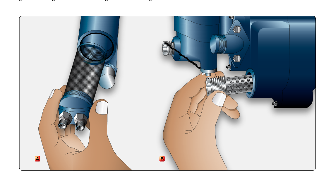
Before oil reaches the bearings, it passes through an oil filter—usually a fine-mesh wire screen or a paper-element filter designed to trap contaminants down to the micron rating specified by the engine manufacturer. A filter bypass valve opens if the filter becomes clogged, allowing oil to continue flowing to the engine at the cost of unfiltered lubrication. Many systems include a chip detector downstream of the scavenge filter to capture ferrous particles and alert maintenance personnel to abnormal wear.
To prevent oil temperatures from rising excessively, an oil cooler is placed in the pressure circuit. In most turbofan engines, the oil cooler is a fuel-cooled oil cooler (FCOC), meaning that fuel flowing to the combustion chamber absorbs heat from the oil. This simultaneously cools the oil and warms the fuel—improving combustion efficiency. Some engines also use an air-cooled oil cooler as a supplementary or backup device. A thermostatic bypass valve routes oil around the cooler when oil temperature is low, preventing excessively cold, viscous oil from reaching the bearings on cold-weather starts.
The Scavenge Subsystem
After oil has done its work lubricating bearings and gears, it collects in the bearing sumps—sealed compartments that surround each bearing location. The scavenge subsystem's job is to remove this hot, aerated oil from the sumps and return it to the tank as quickly as possible. Efficient scavenging is critical: if oil is allowed to pool in a hot sump, it can coke (carbonize), degrading lubrication quality and potentially causing bearing damage.
Scavenge is accomplished by scavenge pumps—also positive-displacement gear pumps driven by the accessory gearbox. A key design principle is that total scavenge pump capacity exceeds pressure pump capacity, since the exact margin varies by engine design; always consult the manufacturer's maintenance manual for specific figures. This over-capacity ensures the sumps are never overwhelmed by returned oil even when large volumes of air are entrained in the scavenge flow. Because each bearing sump may be in a different location in the engine, most designs use multiple scavenge elements, sometimes in a single multi-element pump block, each element dedicated to one or more sumps.
Scavenged oil passes through a scavenge filter (often with its own chip detector) before returning to the tank. The deaerator in the tank then removes the air and foam from the scavenged oil before it recirculates through the pressure subsystem. In a hot-tank system, the oil returns to the tank before passing through the oil cooler, so tank oil is at elevated temperature. In a cold-tank system, the oil is cooled before returning to the tank, so stored oil remains cooler. Most modern high-bypass turbofan engines use the hot-tank configuration.
The Breather (Vent) Subsystem
Even the best shaft seals allow some air to leak into the bearing sumps from the compressor stages, and oil mist inevitably becomes entrained in this air. The breather subsystem manages this mixture of air and oil vapor to prevent pressure buildup inside the sumps (which would blow oil past seals) and to recover as much oil as possible before venting to the atmosphere.
Air from the sumps and oil tank flows to a breather pressurizing valve and then to a centrifugal breather or oil separator. The centrifugal breather spins the air-oil mixture at high speed; centrifugal force flings the heavier oil droplets outward to a collection surface, where they drain back to the scavenge circuit. The cleaned air is then vented overboard through a breather tube, typically exiting at the engine nacelle or a dedicated vent port.
The system is designed so that the oil tank and sumps are maintained at a slightly higher pressure than ambient. Some engine designs accomplish this by routing compressor bleed air to pressurize the tank and sumps, while many others rely on the breather/vent system itself, combined with the pressurizing valve, to maintain this slight positive pressure without dedicated bleed air; the specific method depends on engine design. This positive pressure prevents foaming and ensures consistent oil delivery to the pressure pump. However, this also means that if the breather system becomes blocked, dangerously high pressures can develop, forcing oil out past seals and potentially causing an oil fire.
Why It Matters for AMTs
Understanding the three subsystems is directly relevant to troubleshooting and maintenance decisions. A rapid drop in oil pressure most often points to the pressure subsystem—a failed pump, clogged filter (check for a bypass indication), or failed relief valve stuck open. Conversely, high oil temperature can indicate a failed oil cooler thermostatic valve, a blocked FCOC, or inadequate scavenge flow causing oil to pool in hot sumps. Evidence of oil leaks at the sump seals or excessive oil consumption often points to a breather subsystem fault—a clogged separator or a pressurization imbalance forcing oil past air seals.
Chip detectors deserve particular attention. When a chip detector triggers, the maintenance manual will direct specific actions—often including cutting the oil filter open and inspecting the element for the type, size, and quantity of particles. Ferrous fuzz (fine, soft particles) may indicate normal break-in wear, while larger chips or non-ferrous particles can signal an imminent bearing failure requiring removal of the engine from service.
Key Numbers and Rules
- Expansion space: Oil tanks must include approximately 10 percent volume for thermal expansion and foam.
- Scavenge-to-pressure ratio: Scavenge pump capacity is always greater than pressure pump capacity to ensure sump drainage even with aerated oil; the exact margin is engine-specific, so consult the manufacturer's maintenance manual.
- Filter bypass valve: Opens automatically when a clogged filter creates excessive differential pressure, allowing unfiltered oil flow to continue.
- Oil cooler type: Most modern turbofans use a fuel-cooled oil cooler (FCOC); some add air-cooled coolers. Thermostatic valves bypass the cooler during cold starts.
- Hot-tank vs. cold-tank: Hot-tank systems cool oil after the tank; cold-tank systems cool oil before storage. Know which type is on the engine you're servicing.
- Chip detector response: A confirmed chip indication requires oil filter inspection and analysis per the manufacturer's maintenance manual before further flight.
- Breather pressure: Sumps and tank are maintained at slight positive pressure relative to ambient—accomplished via the breather/vent system, and on some engines with compressor bleed air assistance, to prevent pump cavitation and seal blow-out.
Common Test Traps
- Scavenge pump sizing confusion: Students often assume the pressure pump is larger. It is not—scavenge pumps must have greater capacity to handle aerated oil and prevent sump flooding.
- Hot-tank vs. cold-tank mix-up: In a hot-tank system the oil is hot when it enters the tank; in a cold-tank system it has already been cooled. The names refer to the condition of oil in the tank, not the cooler location.
- Bypass valve purpose: The filter bypass valve protects oil flow (not the filter). When it opens, oil continues to flow but unfiltered—this is a degraded, not safe, condition requiring immediate maintenance attention.
- Breather blockage consequence: A blocked breather increases sump pressure, which forces oil past seals causing leaks and potential fire—not simply reduced ventilation.
- Chip detector fuzz vs. chips: Fine metallic fuzz may be considered normal wear in some manuals, but large or hard chips require immediate investigation. Never dismiss a chip detection without the inspection the maintenance manual prescribes.