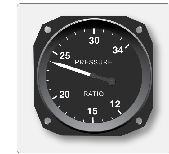
When a turbine engine produces thrust, there is no simple mechanical scale you can read to confirm how hard it is pushing the aircraft. Instead, engineers designed instrument systems that infer thrust from measurable pressures within the engine. Engine Pressure Ratio (EPR) is one of the most direct and widely used of these methods. It compares the total pressure at the turbine exhaust to the total pressure at the engine inlet, producing a dimensionless ratio that rises and falls in close proportion to the actual thrust being generated. Understanding EPR — how it is measured, why it works, and where it falls short — is essential knowledge for any Aviation Maintenance Technician working on turbofan-powered aircraft.
Not every turbine engine uses EPR as its primary thrust indicator. Some manufacturers, particularly those producing high-bypass turbofan engines, rely instead on fan speed (N1) as the primary thrust reference. However, on many commercial transport-category powerplants, EPR remains the standard, and the FAA Powerplant knowledge test expects you to understand both its theory and its practical application.
How EPR Works
EPR is defined as the ratio of the total pressure at the turbine exhaust (Pt7) to the total pressure at the engine inlet (Pt2). Written simply: EPR = Pt7 ÷ Pt2. A ratio of 1.0 means exhaust pressure equals inlet pressure — essentially no net work is being done by the engine. As thrust increases, the engine compresses more air, burns more fuel, and expels the exhaust gases at much higher energy, so the exhaust total pressure rises relative to inlet pressure. Typical takeoff EPR values for large turbofans are generally cited in the range of approximately 1.3 to 1.7, though exact figures vary by engine model and ambient conditions and should always be confirmed against the manufacturer's performance data.
The measurement relies on total (stagnation) pressure rather than static pressure alone. Total pressure is the sum of static pressure and dynamic pressure — it represents the full energy content of the airflow at that station. At the inlet, a pitot-type probe senses Pt2. At the exhaust, one or more probes positioned in the exhaust duct or turbine exit plane sense Pt7. These pressure signals are routed to an EPR transmitter or engine data computer, which performs the division and sends the resulting ratio to the cockpit EPR gauge.
The Role of the EPR Transmitter
On older analog systems, a dedicated EPR transmitter (sometimes called a ratio unit) contains a differential pressure mechanism that mechanically or pneumatically computes the ratio and drives a synchro signal to the cockpit instrument. On modern Full Authority Digital Engine Control (FADEC) systems, pressure transducers convert inlet and exhaust pressures into electronic signals, and the engine control computer calculates EPR digitally. The cockpit display may be a traditional round gauge or an Engine Indicating and Crew Alerting System (EICAS) or Electronic Centralized Aircraft Monitor (ECAM) digital readout, but the underlying measurement principle is identical.
Why EPR Is a Good Thrust Indicator
Thrust in a jet engine is fundamentally a product of the mass airflow through the engine and the velocity increase imparted to that air. The total pressure ratio across the engine is thermodynamically linked to both of these quantities. When the engine ingests more air and adds more energy to it, the exhaust total pressure rises proportionally. Because EPR captures this relationship directly from pressure measurements at the two ends of the thermodynamic cycle, it provides a more direct indication of thrust than rotor speed alone.
Rotor speed (N1 or N2) is an indirect indicator because the same RPM can produce different amounts of thrust depending on air density, inlet temperature, and compressor efficiency. EPR is also affected by ambient temperature and pressure and, like N1, requires temperature-compensated target tables to produce an accurate thrust reference — it is not inherently self-correcting for all these variables without reference to manufacturer performance data. Still, because EPR is measured directly from pressures at the two ends of the thermodynamic cycle, it tends to reflect actual gas-path energy changes more directly than a simple tachometer reading.
Factors That Affect EPR Readings
Several operational and environmental factors influence the EPR indication, and AMTs must understand them to correctly interpret maintenance data and troubleshoot discrepancies.
- Inlet air temperature (TAT/OAT): Colder, denser air increases mass flow and shifts the EPR-to-thrust relationship. Engine manufacturers publish EPR target tables or thrust management computer algorithms that account for inlet temperature (often expressed as Total Air Temperature, or TAT).
- Altitude and ambient pressure: As altitude increases, ambient pressure falls, and both Pt2 and Pt7 fall with it. EPR does not remain simply constant with altitude for a given thrust level — manufacturers publish altitude-corrected EPR schedules precisely because altitude and ambient pressure changes affect the EPR-to-thrust relationship, and these schedules must be consulted for accurate thrust setting at different altitudes.
- Bleed air extraction: Extracting large amounts of compressor bleed air for cabin pressurization or anti-icing reduces the mass flow available to produce thrust. This lowers EPR for a given throttle setting and must be accounted for in performance calculations.
- Engine deterioration: As compressor and turbine blades wear or accumulate deposits, engine efficiency degrades. A deteriorated engine may produce less thrust at a given EPR setting, or conversely may reach its EPR limit at a lower throttle position. Trend monitoring of EPR during standardized test conditions is a key maintenance tool for detecting engine health degradation.
- Probe contamination or blockage: If the inlet or exhaust pressure probes become contaminated with ice, dirt, or foreign material, the EPR indication will be erroneous. A blocked inlet probe can cause an artificially low Pt2 reading, making EPR appear higher than actual — a potentially dangerous condition because the crew may believe more thrust is available than the engine is actually producing.
EPR vs. N1 as a Thrust Reference
The choice between EPR and N1 as the primary thrust indicator is made by the engine manufacturer and depends on the engine's design. High-bypass turbofans, generally understood as having bypass ratios greater than roughly 4:1 or 5:1 (the FAA handbook does not specify one precise universal cutoff), deliver a large fraction of their total thrust through the fan stream rather than the core exhaust. On these engines, fan speed (N1) correlates well with total thrust because the fan dominates the propulsive output. Engines with lower bypass ratios or older designs may use EPR because the core exhaust velocity is a larger fraction of total thrust, making the exhaust pressure a better indicator.
From a maintenance standpoint, understanding which parameter is primary for a given engine type is critical. When performing ground runs, acceptance checks, or troubleshooting, the AMT must reference the correct primary thrust parameter for that engine, consult the applicable Engine Manual or Aircraft Maintenance Manual (AMM), and compare readings against the manufacturer's performance tables for the prevailing atmospheric conditions.
Key Numbers and Rules
- EPR = Pt7 ÷ Pt2 — always exhaust pressure divided by inlet pressure.
- An EPR of 1.0 indicates no net pressure rise from inlet to exhaust — essentially idle or windmilling conditions.
- Takeoff EPR values are engine-model specific; always consult the manufacturer's performance data. Typical transport-category values are commonly cited roughly in the 1.3 to 1.7 range, though this varies by engine type.
- EPR is a dimensionless ratio — it has no units.
- EPR target values for a given thrust setting are corrected for inlet total temperature and altitude/ambient pressure, so the crew or FMC must reference correct temperature and altitude data for accurate thrust management.
- A blocked or iced inlet probe lowers the sensed Pt2, which causes a falsely high EPR reading — the engine appears to be producing more thrust than it actually is.
- Bleed air extraction reduces available thrust for a given EPR setting and must be factored into takeoff performance calculations.
Common Test Traps
- Confusing the pressure stations: EPR is exhaust divided by inlet, not the other way around. Reversing the ratio gives a number less than 1.0 at normal power, which is physically meaningless for EPR and a classic distractor on the knowledge test.
- Assuming EPR is universal: Some high-bypass turbofan engines use N1, not EPR, as the primary thrust indicator. The test may ask which parameter is primary — always identify the engine type and its design philosophy first.
- Ignoring probe failure modes: A blocked inlet probe causes falsely HIGH EPR (Pt2 is erroneously low). A blocked exhaust probe causes falsely LOW EPR. Students often mix these up under exam pressure.
- Overlooking bleed air effects: Questions about EPR accuracy or thrust shortfall often hinge on whether bleed air extraction was considered. Large bleed loads can cause a meaningful thrust reduction at a constant EPR setting.
- Treating EPR as an absolute thrust number: EPR is a ratio, not a pounds-of-thrust readout. The actual thrust produced at a given EPR depends on ambient conditions, so performance tables — not the gauge alone — give the final answer on available thrust.