At the heart of every modern turbofan and turbojet lies a component that must take a large mass of ambient air and compress it to many times atmospheric pressure before it ever reaches the combustor. The axial-flow compressor accomplishes this feat by accelerating air rearward through a series of rotating blades, then decelerating and straightening that air through stationary vanes — converting kinetic energy into pressure rise in repeated, controlled increments. Understanding how each stage contributes to overall compression, why multiple stages are required, and how the design of individual airfoil rows governs performance is foundational knowledge for any powerplant technician and is thoroughly addressed in FAA maintenance and knowledge test materials.
This article walks through the aerodynamic principles behind axial-flow compression, the anatomy of a single stage, how stage pressure ratios stack together, and the practical design choices — rotor blade angle, stator geometry, and stage loading — that define modern high-bypass engine compressor sections.
Basic Aerodynamic Principle
An axial-flow compressor works on the same fundamental principle as a wing: shaped airfoils moving through air produce a lift force. In the compressor, that "lift" is directed so that the rotor blades do work on the air, accelerating it and raising its total energy. When the accelerated air then passes through the stationary stator vanes that follow each rotor row, its velocity decreases and static pressure rises — a process called diffusion. The stator row also removes the swirl imparted by the rotor, realigning airflow in a nearly axial direction so it enters the next rotor row at the correct angle.
This sequence — rotor accelerates, stator diffuses and straightens — constitutes one compressor stage. Each stage produces a modest pressure ratio, typically in the range of 1.1:1 to 1.4:1 in a conventional design. Because the ratios multiply rather than add, stacking many stages yields the high overall pressure ratios (OPRs) needed for efficient combustion. A 20-stage compressor with an average stage pressure ratio of 1.3:1 can theoretically reach an OPR exceeding 19:1, though aerodynamic and mechanical losses reduce the practical value.
Anatomy of a Single Stage
Rotor Blades
Rotor blades are attached to a disk that is driven by the turbine section through a central shaft. Their airfoil shape is twisted along the span — more cambered and at a higher angle near the root where blade speed is lower, flatter and at a lower angle near the tip where blade speed is higher. This twist ensures that every radial section of the blade operates at a similar angle of attack despite the large difference in rotational velocity from hub to tip. The FAA Aviation Maintenance Technician Handbook — Powerplant (FAA-H-8083-32) describes how rotor blades must be precisely contoured and free of nicks, dents, or corrosion because even minor surface damage disrupts the boundary layer and reduces stage efficiency dramatically.
Stator Vanes
Stator vanes are fixed to the engine case and form a diverging passage (a diffuser) between adjacent vanes. As the higher-velocity air from the rotor enters this expanding passage, it slows down and its static pressure rises. Stator vanes also redirect the flow back toward the axial direction, setting the proper inlet angle for the next rotor row. In many engines, the first few stator stages are variable stator vanes (VSVs) — their pitch angle can be adjusted by the engine's fuel control or FADEC system in response to throttle position and flight conditions. Variable vanes prevent compressor stall during acceleration and at off-design operating conditions.
Inlet Guide Vanes
Ahead of the first rotor stage, many axial compressors incorporate inlet guide vanes (IGVs), which pre-swirl the incoming air in the direction of rotor rotation. This reduces the relative velocity seen by the first-stage rotor blades, lowering the risk of shocks and improving efficiency at the design point. IGVs are frequently variable as well, managed alongside the VSVs by the engine control system.
Stage Pressure Ratio and Its Governing Factors
The pressure rise produced by a single stage depends on three primary variables: blade tip speed, blade camber and airfoil efficiency, and mass flow and axial velocity. Of these, tip speed has the strongest effect. Because pressure rise is proportional to the square of blade velocity (following Euler's turbomachinery equation), engineers push tip speeds as high as material strength and compressibility limits allow. Modern titanium alloy blades in high-pressure compressors operate at tip speeds approaching or slightly exceeding the speed of sound, entering the transonic regime. In transonic stages, a weak shock wave forms on the blade surface and is used deliberately to add an additional pressure jump — allowing stage pressure ratios as high as 1.6:1 to 1.8:1 or more in the first fan or high-pressure stages of advanced engines.
The degree of reaction describes how the total pressure rise of a stage is divided between the rotor and the stator. A 50-percent reaction stage — common in many designs — splits the pressure rise equally: the rotor raises static pressure by one portion while also increasing velocity, and the stator converts the velocity increase into an equal static pressure rise. Adjusting the reaction changes blade loading and influences susceptibility to stall.
Overall Pressure Ratio and Multi-Spool Architecture
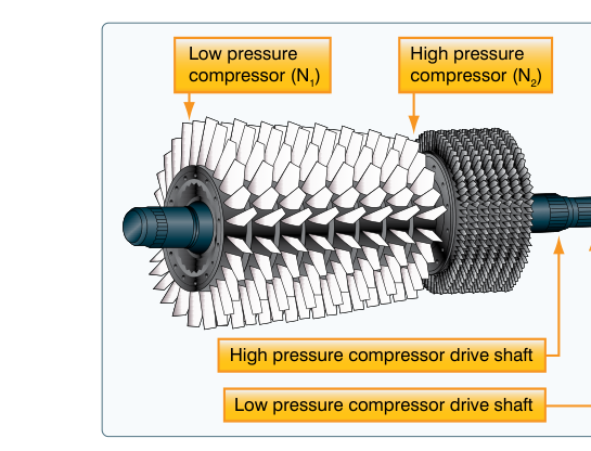
Modern high-bypass turbofan engines achieve overall pressure ratios of 30:1 to more than 50:1. Reaching these ratios with acceptable efficiency and stall margin requires splitting the compressor into two or three separate spools, each rotating at its own optimal speed. A typical two-spool engine has a low-pressure compressor (LPC), or booster, driven by the low-pressure turbine, and a high-pressure compressor (HPC) driven by the high-pressure turbine. Each spool is matched to its own pressure and temperature environment, allowing rotor speeds and blade geometries to be optimized independently. Three-spool designs add an intermediate-pressure compressor on a third shaft, providing even finer matching across the full operating envelope.
The FAA Powerplant handbook notes that as air progresses through the compressor, it grows hotter and denser. Blade height decreases progressively from front to rear because the compressed air occupies less volume. This is why the distinctive convergent annular shape is visible when viewing a disassembled axial compressor — tall, widely-spaced blades at the low-pressure inlet give way to short, closely-packed blades at the high-pressure exit.
Why Design Details Matter for Maintenance
Every aspect of axial-flow compressor design has direct maintenance implications. Blade airfoil contour tolerances are extremely tight; a blade that has been bent, eroded, or improperly repaired changes the passage area and disrupts the designed pressure rise. Foreign object damage (FOD) that nicks leading edges can trigger flow separation and compressor stall. Stator vane trailing edge damage alters the swirl angle entering the downstream rotor, compounding efficiency losses stage by stage.
Variable stator vane actuating rings, feedback rods, and bushings must be inspected for wear and rigging accuracy. Incorrect VSV scheduling — whether from mechanical wear or a faulty position sensor — can push the operating line toward the stall limit at part-power settings, manifesting as a compressor surge or stall that the crew experiences as a loud bang and momentary loss of thrust.
Key Numbers and Rules
- Typical stage pressure ratio: 1.1:1 to 1.4:1 for subsonic stages; up to 1.6:1–1.8:1 or higher for transonic stages.
- Overall pressure ratio (OPR): Modern high-bypass turbofans commonly achieve 30:1 to 50:1 or more; older engines may be 15:1 to 25:1.
- Stage count: High-bypass engines typically have 6 to 17 or more HPC stages combined with LPC stages to reach design OPR.
- Stall margin: Designers maintain a stall margin — a buffer between the operating line and the surge/stall line on the compressor map — to accommodate transient conditions such as rapid throttle advancement and inlet distortion.
- Blade material: Front stages often use titanium alloys for light weight; rear HPC stages use nickel alloys to withstand high temperatures (400–500°C or more).
- Variable vane systems: VSVs and IGVs are modulated by FADEC/engine control unit (ECU) as a function of corrected speed (N/√T) to maintain proper incidence angles off-design.
- Blade height trend: Blade height decreases from front to rear as air density increases through compression, maintaining roughly constant axial velocity through the stages.
Common Test Traps
- Confusing rotor and stator functions: The rotor adds energy (velocity and pressure) to the air; the stator converts velocity to static pressure and removes swirl. Exam questions sometimes ask which component causes the primary static pressure rise — both do, but in different ways within each stage.
- Assuming pressure ratios add: Stage pressure ratios multiply, not add. A three-stage compressor with 1.3:1 per stage produces 1.3 × 1.3 × 1.3 = 2.197:1, not 3.9:1. This is a classic calculation trap.
- Mixing up axial-flow and centrifugal compressors: Centrifugal compressors discharge air radially outward through a diffuser; axial-flow compressors keep airflow roughly parallel to the engine axis. The FAA test distinguishes these clearly, including that centrifugal designs achieve a higher single-stage pressure ratio but lower overall efficiency at high OPRs.
- Forgetting variable vane purpose: Candidates sometimes state that VSVs vary thrust — they do not directly. VSVs optimize incidence angle to prevent stall at off-design conditions; thrust is controlled by fuel flow.
- Ignoring blade height convergence: Some candidates expect uniform blade dimensions throughout the compressor. The progressive decrease in blade height is a direct consequence of increasing air density and is a frequently tested detail in compressor identification questions.