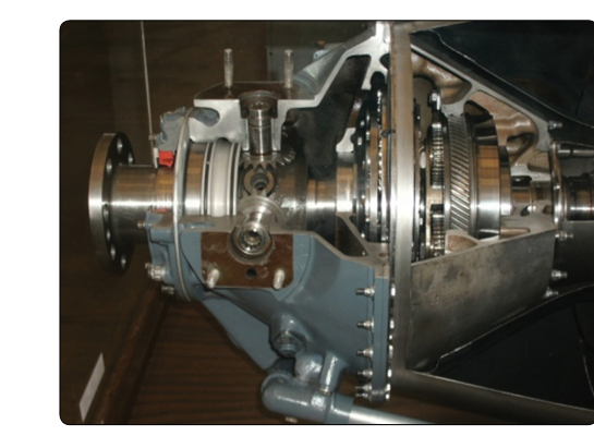
A turboprop engine is essentially a gas turbine whose primary job is to drive a propeller rather than produce jet thrust. The combustion gases spin a power turbine at tens of thousands of revolutions per minute — far too fast for any propeller to operate efficiently or safely. The reduction gearbox bridges this gap, slashing turbine RPM down to the few hundred or low-thousand RPM range that a propeller demands while simultaneously multiplying torque. Understanding how this system works, how it is maintained, and what can go wrong is fundamental knowledge for any Aviation Maintenance Technician (AMT) seeking a Powerplant certificate.
The propeller coupling is equally important: it is the mechanical interface that physically connects the gearbox output shaft to the propeller hub, transmitting torque while accommodating thermal expansion, slight misalignment, and the shock loads of normal flight. Together, the reduction gearbox and propeller coupling define much of the reliability, efficiency, and maintenance burden of any turboprop installation.
Why a Reduction Gearbox Is Necessary
Gas turbine power sections and power turbines are optimized to spin at very high rotational speeds — typically between 20,000 and 40,000 RPM in light turboprop engines, and somewhat lower in large turboshaft designs. A propeller, by contrast, is limited by tip speed. As a propeller blade tip approaches the speed of sound, efficiency drops sharply and noise becomes extreme. For most propellers, this constrains practical speeds to roughly 1,000–2,000 RPM for large-diameter blades, and up to about 2,400 RPM for smaller high-performance designs. The ratio between the power turbine speed and the propeller output speed is the reduction ratio, often expressed as a gear ratio such as 15:1 or 20:1. At a 15:1 ratio, if the power turbine turns at 30,000 RPM, the propeller shaft turns at 2,000 RPM.
The laws of mechanics dictate that reducing rotational speed through gearing simultaneously multiplies torque by approximately the same ratio (minus frictional losses). A turboprop power turbine might produce relatively modest torque but enormous RPM; the gearbox converts this into the high-torque, moderate-RPM output that swings a large propeller blade through dense air. This torque multiplication is why turboprops can swing very large, high-thrust propellers that piston engines of comparable power cannot.
Types of Reduction Gearbox Designs
Several gear configurations are used in turboprop reduction gearboxes, each with trade-offs in weight, complexity, reliability, and reduction ratio capability.
- Spur gear systems: The simplest design, using parallel-shaft gears. Spur gears are mechanically straightforward but can produce noise and are limited in the reduction ratios achievable in a single stage without becoming excessively large and heavy.
- Helical gear systems: Teeth are cut at an angle to the gear axis, allowing multiple teeth to mesh simultaneously. This produces smoother, quieter operation and higher load capacity than spur gears. Many turboprop gearboxes use helical gears for this reason.
- Planetary (epicyclic) gear systems: A central sun gear meshes with several planet gears that rotate around it and are themselves carried by a rotating planet carrier, all inside a fixed or rotating ring gear. Planetary systems allow very high reduction ratios in a compact, lightweight package with load shared across multiple gear mesh points. Many modern turboprop engines — including engines in the PT6 family (referenced in FAA training materials as representative designs) — use planetary reduction gearing because of its favorable power-to-weight ratio and smooth power transmission.
Most turboprop gearboxes are located at the front of the engine and are either in-line (propeller shaft on the same centerline as the power turbine shaft) or offset (propeller shaft displaced from the turbine centerline). Some designs incorporate an internal torquemeter — a device that measures the torsional load in the shaft system — which allows cockpit torque gauges to provide the crew and maintenance personnel with direct indication of power output.
Lubrication of the Reduction Gearbox
The reduction gearbox operates under very high loads and generates significant heat. It requires a dedicated pressure lubrication system using turbine-grade oil (typically MIL-PRF-23699 or equivalent synthetic lubricant). Oil is pressure-fed to all gear mesh points and bearings, then collected in a sump and returned by scavenge pumps to the oil tank for cooling and re-circulation. Many gearbox designs share the engine's main oil system, while others have a separate dedicated gearbox oil system. Magnetic chip detectors are installed in the gearbox oil passages; any ferrous metal particles that collect on the detector signal bearing or gear wear and trigger maintenance action before a catastrophic failure can occur. Oil filter condition and chip detector inspections are among the most critical routine maintenance checks on a turboprop.
Propeller Coupling
The propeller coupling is the structural and mechanical interface between the gearbox output shaft and the propeller. Its primary functions are to transmit torque reliably, secure the propeller against axial (forward and aft) loads and centrifugal loads, and accommodate small degrees of misalignment and thermal expansion without introducing harmful stresses.
The most common coupling method on turboprop engines is the splined shaft with a retaining nut or flange. The gearbox output shaft has external splines that mate with internal splines in the propeller hub or propeller shaft adapter. Splines distribute the torque load over a large contact area rather than concentrating it at a single keyway, greatly improving fatigue life. A large retaining nut, secured with the manufacturer-specified torque and typically safety-wired or staked to prevent loosening, secures the propeller axially on the shaft.
Some installations use a curvic coupling or a flange coupling, in which mating precision-machined flanges are bolted together with high-strength fasteners. Flange couplings offer excellent concentricity and are common on larger turboprop and turboshaft installations. The fastener torque values, inspection intervals, and any special tooling requirements are always specified in the engine manufacturer's maintenance manual and must be followed exactly — there is no acceptable improvisation when coupling a propeller to a gas turbine gearbox.
Propeller Shaft Inspection and Maintenance
The propeller shaft and coupling components are subject to rigorous inspection requirements. AMTs must check for:
- Corrosion and fretting: Spline wear and fretting corrosion where spline flanks contact each other. Even small amounts of fretting can indicate improper fit or lubrication and must be evaluated against the manufacturer's limits before the propeller is re-installed.
- Crack detection: Propeller shafts and flanges are typically inspected using magnetic particle inspection (for ferrous components) or fluorescent penetrant inspection (for non-ferrous and ferrous components) at intervals specified in the maintenance manual or whenever a propeller strike or hard landing occurs.
- Dimensional inspection: Spline dimensions, shaft runout, and flange flatness are measured and compared to manufacturer tolerances. Out-of-tolerance components must be repaired or replaced — never returned to service beyond limits.
- Torquemeter system: Where installed, the torquemeter components in or near the coupling area must be inspected and calibrated to ensure accurate power readings.
Propeller Strike Considerations
A propeller strike — any event in which a propeller blade contacts an object, or the engine is subjected to a sudden stoppage — creates potential damage not just to the propeller but throughout the entire reduction gearbox and propeller coupling. The sudden deceleration can cause micro-cracking in gear teeth, bearing races, and the propeller shaft itself, none of which may be visible to the naked eye. FAA guidance and engine manufacturer instructions typically require a complete gearbox teardown inspection after any propeller strike or sudden stoppage event. Returning an engine to service after a propeller strike without the required inspection is a serious safety violation.
Key Numbers and Rules
- Typical turboprop power turbine speeds: 20,000–40,000 RPM (varies by engine design).
- Typical propeller output speeds: 1,000–2,400 RPM depending on propeller diameter and design.
- Common reduction ratios: 10:1 to 20:1 or higher, depending on the engine.
- Turbine oil type: typically Type II synthetic turbine oil (MIL-PRF-23699 or equivalent) — never substitute automotive or piston-engine oil.
- Chip detectors must be inspected at manufacturer-specified intervals and after any abnormal event.
- Propeller retaining nut torque and safety-wiring must follow the engine/propeller manufacturer's maintenance manual exactly.
- Propeller strike requires mandatory gearbox teardown inspection per manufacturer instructions before return to service.
Common Test Traps
- Confusing speed and torque relationships: Students often forget that reducing speed through a gearbox multiplies torque. The gearbox does not create power — it converts high-speed, low-torque input into low-speed, high-torque output, with small losses to friction.
- Assuming a propeller strike is only a propeller problem: The FAA and manufacturers are clear — a propeller strike or sudden stoppage demands gearbox inspection, not just propeller replacement. Failing to do so is an airworthiness issue.
- Oil type substitution: Using the wrong oil in a turbine gearbox (for example, piston-engine oil) can rapidly destroy bearings and gears. The question may ask about lubrication requirements; the answer is always the manufacturer-specified synthetic turbine oil.
- Chip detector findings: A chip detector with collected particles is a mandatory maintenance action, not a monitor-and-continue situation. Even small amounts of ferrous debris indicate internal wear.
- Reduction ratio direction: Test questions may ask which component turns faster. Remember: the power turbine shaft always turns faster than the propeller shaft. The ratio is always turbine RPM divided by propeller RPM.