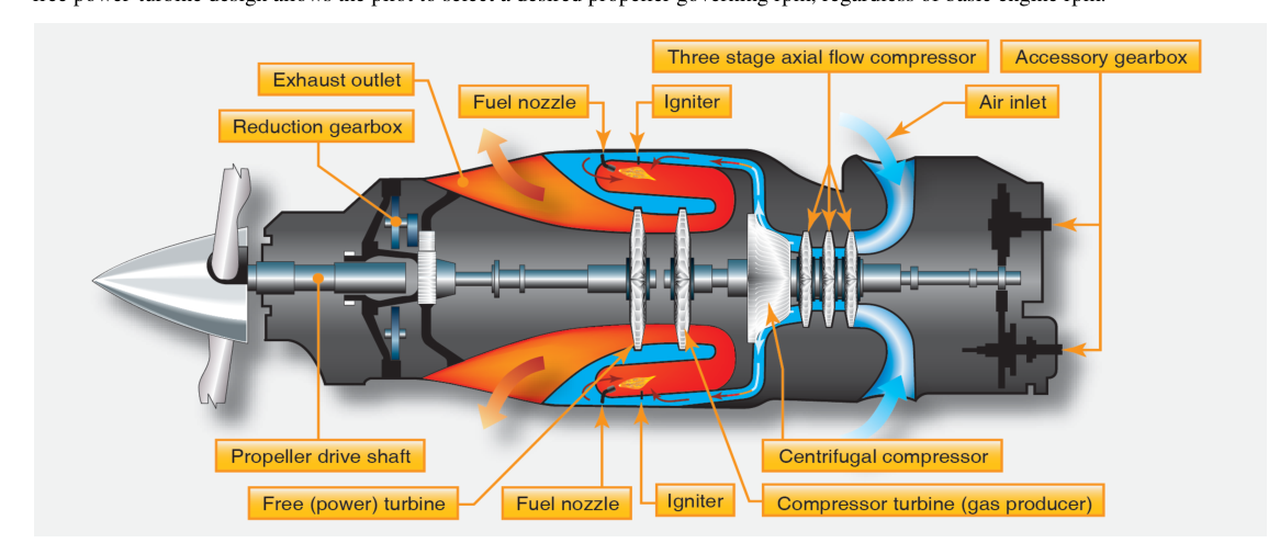
The turboshaft engine is one of the most versatile members of the gas turbine family. Unlike a turbojet, which accelerates exhaust gases to produce thrust directly, or even a turbofan, which moves a large bypass airstream, the turboshaft dedicates virtually all of the energy extracted from combustion to turning a mechanical output shaft. That shaft power — expressed in shaft horsepower (SHP) — can drive helicopter rotor systems, marine propellers, electrical generators, or any other rotating load. Understanding how the power turbine and output shaft are designed helps an aviation maintenance technician (AMT) maintain these engines safely and reason clearly about what happens when something goes wrong.
Turboshaft engines are the powerplant of choice for helicopters because rotary-wing aircraft need large amounts of torque at relatively low rotational speeds, not jet thrust. They are also widely used in turboprop aircraft (where an additional reduction gearbox connects the shaft to a propeller), in auxiliary power units (APUs), and in many industrial and marine applications. The design principles covered in this article apply broadly across all these uses, and they form a solid foundation for the FAA Aviation Mechanic Powerplant knowledge test.
How the Turboshaft Engine Produces Shaft Power
A turboshaft engine shares its basic thermodynamic cycle — the Brayton cycle — with every other gas turbine. Air enters the inlet, is compressed by one or more stages of axial or centrifugal compressors, is mixed with fuel and burned in the combustion section, and the resulting high-energy gas stream is then expanded through a turbine section. What makes the turboshaft unique is what happens in that turbine section and how the remaining gas energy is handled afterward.
In most turboshaft designs, the turbine section is divided into two functionally separate parts. The gas generator turbine (sometimes called the compressor turbine or N1 turbine) extracts just enough energy from the expanding gases to drive the compressor and engine accessories — nothing more. The gas leaves the gas generator turbine still carrying substantial energy in the form of pressure, temperature, and velocity. This remaining energy is then captured by the power turbine (also called the free turbine or N2 turbine), which is mechanically independent from the gas generator. The power turbine converts this residual gas energy into shaft rotation and delivers it through the output shaft to the driven load.
The Free Power Turbine: Design and Operation
The defining characteristic of most turboshaft architectures is that the power turbine is aerodynamically coupled to the gas generator but mechanically uncoupled from it. There is no physical shaft connecting the two rotors; instead, the fast-moving exhaust gas from the gas generator turbine impinges on the power turbine blades and spins them. This arrangement is commonly called a free turbine design.
The free turbine concept offers several important advantages. Because the power turbine speed is not locked to the compressor speed, engine designers can optimize compressor speed independently of output shaft speed. In a helicopter, the main rotor must turn at a relatively constant speed to maintain aerodynamic efficiency; the free turbine allows the gas generator to vary its speed (throttle up or down) while the power turbine — and therefore the rotor — maintains a nearly constant RPM. This is essential for helicopter operability. Additionally, on engine start, the starter only needs to spin the gas generator section; the power turbine and its attached gearbox are not part of that initial rotating mass, making starting easier and reducing wear.
Power turbine stages are typically one or two stages of axial turbine wheels. Each stage consists of a stationary nozzle ring (stator vanes) that accelerates and directs the gas onto the rotating turbine blades at the optimum angle, followed by the rotating turbine wheel that extracts energy. The blades are designed to handle gas temperatures that can exceed 1,000°C (approximately 1,800°F), so they are commonly cast from high-temperature nickel-based superalloys and may incorporate internal cooling passages, thermal barrier coatings, or directional solidification to resist creep and oxidation.
The Output Shaft and Power Transmission
The power turbine rotor is connected to the output shaft, which transmits torque to the reduction gearbox and ultimately to the driven load. In helicopter applications, the output shaft typically exits from the rear of the engine (though front-drive configurations exist) and connects to a combining gearbox or main gearbox that steps down RPM from turbine speed — which may range from roughly 20,000 to 50,000 RPM depending on engine design — to the much lower rotor RPM, typically around 200 to 300 RPM for large helicopter main rotors.
The output shaft itself must be designed for both high torque and the torsional vibrations inherent in turbine engine operation. It is typically made from high-strength alloy steel and is carefully balanced during manufacture. Many designs incorporate a torquemeter — a device that measures twist (torsional deflection) in the shaft and converts it to a torque reading in the cockpit. This is important because torque is the primary power indicator in turboshaft and turboprop engines, serving a role analogous to manifold pressure in piston engines. Pilots and maintenance technicians rely on torque limits to prevent overloading both the engine and the driven gearbox.
Some turboshaft engines place the output shaft at the front of the engine, requiring the power turbine shaft to pass through the center of the gas generator section — a concentric or nested shaft arrangement. This is mechanically complex but allows for a more compact installation in some airframes. Bearing selection, lubrication routing, and thermal expansion management become critical engineering considerations in such designs.
Why the Power Turbine Design Matters for Maintenance
From an AMT perspective, understanding the free turbine arrangement clarifies why certain inspections and limits exist. Because the power turbine and gas generator can spin at different speeds, each rotor has its own tachometer sensing system. A discrepancy between N1 (gas generator speed) and N2 (power turbine/output shaft speed) that is outside of normal operating relationships can indicate a problem such as a failed power turbine blade, a sheared coupling, or a seized gearbox.
Power turbine blades are subject to extreme centrifugal loads combined with high gas temperatures — two conditions that promote creep (slow permanent deformation under stress at elevated temperature). Manufacturers set strict limits on turbine blade tip clearance, blade elongation, and surface condition. Hot section inspections, often guided by the engine manufacturer's maintenance manual and supported by borescope examination, are the primary means of assessing power turbine condition without full disassembly. AMTs must look for cracking, oxidation, erosion from ingested debris, and evidence of tip rubs where blades contact the shroud ring.
The output shaft and its associated couplings must be inspected for fretting, corrosion, and spline wear. Torque limits during ground runs and flight operations protect the shaft from overload, but maintenance records should always be reviewed for any history of overtorque events, as these require specific inspections per the engine manufacturer's instructions.
Key Numbers and Rules
- Power output unit: Turboshaft power is measured in shaft horsepower (SHP) or kilowatts (kW); residual exhaust thrust is typically negligible and may be expressed as equivalent shaft horsepower (ESHP) for turboprops.
- Gas generator speed (N1): Typically expressed as a percentage of a design RPM value, often in the range of 20,000–50,000 physical RPM depending on engine size.
- Power turbine speed (N2): Also expressed as a percentage; in free-turbine designs, N2 can vary somewhat independently of N1.
- Torque limits: Each engine has a maximum continuous torque and a transient (takeoff) torque limit; exceeding these requires an unscheduled inspection per the manufacturer's maintenance manual.
- Turbine inlet temperature (TIT) or interstage turbine temperature (ITT): The primary thermal limit; exceeding limits even briefly can cause accelerated creep and blade failure.
- Hot section inspection intervals: Determined by manufacturer and may be reduced after any overtemperature or overtorque event.
Memory Aid
"GAS then FREE" — a simple reminder of the two-turbine sequence in a turboshaft:
- Gas generator turbine: drives the compressor (and accessories), does not connect to the output shaft.
- Aerodynamic coupling only: the power turbine is driven by gas flow, not a mechanical link.
- Shaft output: all remaining gas energy goes to the power turbine and out the shaft.
- FREE: the power turbine is a free turbine — free to vary speed relative to the gas generator, enabling constant rotor RPM control.
Common Test Traps
- Confusing N1 and N2 functions: Remember that the gas generator (compressor) speed and the power turbine/output shaft speed are separate spools in a free-turbine turboshaft. Labeling conventions vary by manufacturer — some use N1/N2, while others use Ng (gas generator) and Np or Nf (power turbine) — so do not assume N1/N2 is a universal standard.
- Assuming mechanical linkage between rotors: Many students assume both turbine sections are on the same shaft. In a free-turbine design they are not — this is precisely what allows the gas generator to spool down or stop independently of the power turbine and output shaft, which continue to be driven by windmilling airflow (as in an engine-off autorotation), without stalling the compressor.
- Neglecting the torquemeter as a power indicator: Questions about turboshaft/turboprop power indication often expect torque (not RPM or EGT alone) as the primary power reference, analogous to MAP in piston engines.
- Overlooking overtorque inspection requirements: A question may describe an overtorque event and ask what is required. The answer is always a specific unscheduled inspection per the engine manufacturer's instructions — simply logging the event and continuing is not acceptable.
- Misidentifying exhaust thrust contribution: In a true turboshaft, the design goal is to extract nearly all gas energy in the power turbine; residual exhaust thrust is minimal. Confusing turboshaft with turbojet thrust production is a classic distractor.