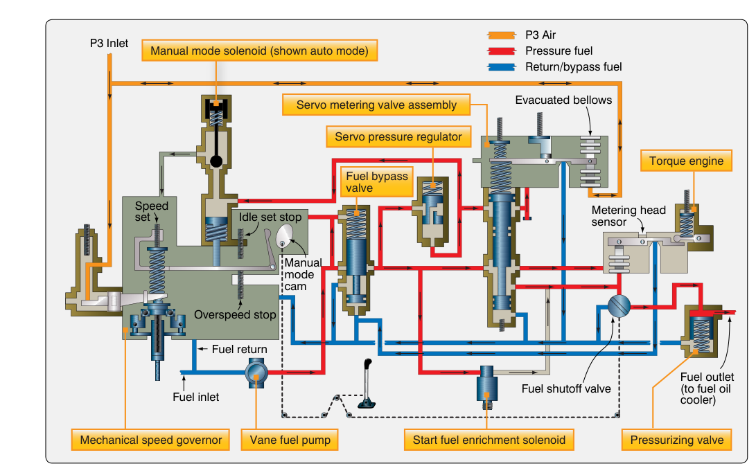
The fuel control unit (FCU) sits at the heart of every turbine powerplant, performing one of the most safety-critical jobs in aviation: delivering exactly the right quantity of fuel, at exactly the right pressure, at exactly the right moment. Too much fuel and the engine surges, overtemps, or suffers a rich blowout; too little and it leans out into a flameout. The FCU prevents both extremes by continuously monitoring a set of engine and atmospheric variables and translating them into a precise metered flow. Understanding how this system works is essential knowledge for any AMT working on turbine powerplants, and it is a recurring subject on the FAA Powerplant knowledge test.
Modern FCUs evolved from purely mechanical hydromechanical units into sophisticated hydromechanical/electronic hybrids, but the underlying metering principles remain the same. This article focuses on the hydromechanical core — the system of pressurized fuel, variable orifices, servo valves, and mechanical computing that governed turbine engines for decades and still forms the baseline of more advanced full-authority digital engine control (FADEC) systems.
The Purpose of Fuel Metering in Turbine Engines
Unlike a reciprocating engine, which operates across a relatively narrow speed and load range, a turbine engine must function efficiently from sea-level static conditions at takeoff power to high-altitude cruise, through acceleration and deceleration transients, and during rapid throttle movements. At each point the combustion section needs a fuel-air ratio that falls within the flammability limits of the fuel (though the primary zone of the combustor operates at near-stoichiometric locally). Too rich causes rich blowout and excessive turbine inlet temperature (TIT); too lean causes lean blowout or flameout. The FCU's job is to keep metered flow inside that safe corridor under all conditions.
The FCU also must schedule fuel to prevent compressor surge during acceleration. As the pilot pushes the power lever forward, fuel flow must increase, but if it increases faster than the compressor can build pressure, the engine can surge. The FCU's acceleration schedule limits the rate of fuel increase to stay just below the surge line.
Hydromechanical Metering Principles
A hydromechanical FCU uses fuel itself as both the working fluid for its internal servo mechanisms and, of course, as the metered product. High-pressure fuel from the engine-driven fuel pump enters the FCU. Inside, the unit maintains a constant pressure drop across a variable-area metering valve. This is the fundamental principle: metered flow = constant pressure differential × variable orifice area. By keeping the differential pressure fixed and varying the orifice size, the FCU converts mechanical positioning of a metering valve into a precise, predictable flow rate.
Maintaining Constant Differential Pressure
A pressure-drop regulating valve (sometimes called a pressure-regulating valve or bypass valve) continuously compares the pressure upstream of the metering valve to the pressure downstream of it. If the differential pressure rises above the design value — say because pump output increased — the bypass valve opens slightly and spills excess fuel back to the pump inlet or to a low-pressure return line. If the differential pressure falls, the bypass valve closes proportionally. This feedback loop holds the pressure drop across the metering orifice at a nearly constant, design-specific value, so the only remaining variable controlling flow is orifice area.
The Metering Valve and Computing Mechanisms
The metering valve is positioned by a computing section that takes in multiple inputs simultaneously. In a hydromechanical unit these inputs are sensed mechanically or pneumatically rather than electronically:
- Power lever angle (PLA): The pilot's throttle position is the primary demand input. A cam or linkage translates PLA into a desired fuel flow schedule.
- Compressor inlet total pressure (Pt2): As altitude increases and air density drops, the engine needs proportionally less fuel. A bellows or aneroid capsule measures Pt2 and biases the metering valve to reduce flow at altitude, maintaining a safe fuel-air ratio.
- Compressor discharge pressure (Pd or P3): This reflects the engine's power condition and pressure ratio at any moment. Some FCUs use P3 directly to trim the metering valve, using it as an index of engine operating condition to help fuel flow track engine power output.
- Compressor inlet temperature (Tt2): Hotter air is less dense. A bimetallic element or temperature-sensing bulb adjusts the scheduling to account for inlet temperature, preventing over-fueling on a hot day.
- Engine speed (N1 or N2): A flyweight governor or speed-sensing gear senses rotational speed. The governor limits maximum speed by reducing fuel if a speed limit is reached, and it also contributes to the acceleration schedule.
All of these inputs act on the computing section through a system of levers, cams, bellows, and servo pistons. Their combined mechanical output positions the metering valve to the area that produces the correct fuel flow for the current operating condition. This is called the steady-state fuel schedule.
Acceleration and Deceleration Scheduling
The FCU must treat transient conditions differently from steady state. When the power lever is advanced rapidly, the computing section would, if unconstrained, open the metering valve to the new higher steady-state position immediately. But the compressor rotor cannot accelerate instantly — its inertia means that for a brief period the pressure ratio lags, and the additional fuel would produce a dangerously rich mixture that could surge the compressor or overtemperature the turbine.
To prevent this, the FCU incorporates an acceleration limiter (acceleration bellows or acceleration control). This device senses the rate of change of compressor discharge pressure and limits how quickly the metering valve can open. Fuel flow increases along a controlled ramp — fast enough to accelerate the engine briskly but slow enough that the compressor pressure ratio stays ahead of the fuel schedule. Similarly, a deceleration limiter prevents the metering valve from closing so rapidly that the lean blowout limit is breached during a sudden power reduction.
The Pressurizing and Dump Valve
Downstream of the metering valve, fuel passes through a pressurizing valve (also called a flow divider on some engines) before reaching the fuel nozzles. The pressurizing valve stays closed until fuel pressure reaches a minimum threshold, ensuring that fuel is delivered to the nozzles at sufficient pressure to atomize properly. On shutdown, a dump valve opens and drains the fuel manifold to prevent fuel from dribbling into the combustor and causing a hot section fire. These valves are separate from the FCU itself but are integral to the metering system's safe operation.
Why Hydromechanical Metering Still Matters
Even on aircraft equipped with FADEC, technicians must understand the hydromechanical baseline. FADEC systems use electronic computers to command servo-actuated valves that perform the same pressure-drop-and-variable-orifice function — the physics have not changed, only the means of computing valve position. On older turboprops and turbojets that remain in widespread service, the pure hydromechanical FCU is the only fuel control, so AMTs must be able to troubleshoot, adjust, and replace these units. Common tasks include trimming the maximum speed governor, setting idle fuel flow, and verifying acceleration schedules during ground runs — all documented in the applicable engine maintenance manual and governed by the procedures in FAA-H-8083-32 Aviation Maintenance Technician Handbook — Powerplant.
Key Numbers and Rules
- Constant pressure drop: The FCU holds a fixed, design-specific differential pressure across the metering valve so that flow is determined solely by orifice area.
- Three operating schedules: steady-state (normal power), acceleration (fuel-flow ramp-up rate limited), and deceleration (fuel-flow ramp-down rate limited).
- Governor limits: The speed governor will reduce fuel to prevent exceeding published N1 or N2 limits regardless of pilot PLA input.
- Pressurizing valve threshold: Fuel must reach a minimum pressure before the pressurizing valve opens to ensure proper atomization — this is why engines are slow to light off at very low pump pressures.
- Shutdown dump: The dump valve drains the manifold on shutdown to prevent post-shutdown fires and coking in nozzles.
- Trimming: FCU trim adjustments are made with calibrated tools and must restore engine parameters to values published on the engine data plate or in the Type Certificate Data Sheet (TCDS).
Common Test Traps
- Confusing the bypass valve's role: The pressure-drop regulating (bypass) valve does not control fuel to the engine — it controls the pressure drop across the metering valve. Excess fuel is spilled back, not added downstream.
- Assuming the pilot directly controls flow: The power lever sets a demand, not a direct flow. The FCU's computing section translates that demand through multiple sensed parameters before positioning the metering valve.
- Mixing up acceleration limiter function: The acceleration limiter prevents compressor surge by limiting the rate of fuel flow increase — it does not limit maximum fuel flow during steady state.
- Pressurizing valve vs. dump valve confusion: The pressurizing valve holds fuel back until pressure is adequate for atomization; the dump valve drains the manifold on shutdown. They are separate devices with separate purposes.
- FADEC and hydromechanical differences: FADEC replaces the mechanical computing section with an electronic controller, but the downstream metering hardware — differential pressure control, variable orifice, pressurizing valve — is conceptually identical. The FAA test may ask about the hydromechanical principles even in a FADEC context.