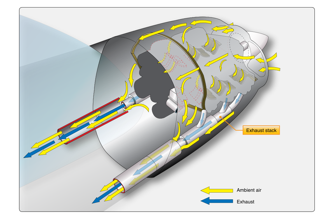
Every aircraft reciprocating engine produces enormous quantities of heat as a byproduct of combustion — heat that must be removed quickly and efficiently to protect cylinders, valves, and surrounding airframe structure. While most pilots are familiar with the classic cowl-flap approach to managing cylinder head temperatures, a significant number of aircraft designs rely on an entirely different mechanism: the augmentor tube exhaust cooling system. Rather than using mechanically operated doors to control airflow, these systems harness the energy already present in the hot exhaust stream to pull cooling air through the engine compartment by suction. Understanding how augmentor systems work, why they were engineered, and how technicians maintain them is essential knowledge for any AMT candidate preparing for the FAA Powerplant knowledge test.
Augmentor cooling is found primarily on horizontally opposed reciprocating aircraft engines, particularly in designs where the manufacturer sought to reduce pilot workload, minimize drag, or eliminate the weight and complexity of cowl flap actuating mechanisms. The system is passive in the sense that it operates automatically whenever the engine is running — there is no cockpit switch, no electric actuator, and no separate control input required. That simplicity is both its greatest advantage and a reason technicians must understand exactly how the physics work to diagnose failures properly.
How the Augmentor System Works
The heart of an augmentor cooling system is the augmentor tube itself — a carefully sized exhaust collector pipe that extends rearward and typically exits beneath the aircraft fuselage or aft of the engine nacelle. Each exhaust collector is positioned so that the exhaust stream exits through the center of a larger outer tube, or shroud. This arrangement creates a concentric duct: hot exhaust gases rush through the inner passage, and ambient cooling air fills the annular space between the inner and outer tubes.
As the high-velocity exhaust gas exits the inner tube, it entrains the surrounding air through the venturi effect and by viscous drag. The rapidly moving exhaust stream creates a low-pressure region at the exit plane, which draws the cooling air along with it and accelerates it rearward. This entrainment action is what gives the system its name — the exhaust gases augment the flow of cooling air that would otherwise depend on ram air and engine-driven airflow alone. In practice, the suction produced by the augmentor tubes pulls airflow into the engine compartment through the forward cowl inlets, across the cylinder fins, through the oil cooler, and ultimately out through the augmentor exit. This directed, continuous airflow removes convective heat from the engine with no moving parts and no pilot intervention.
The quantity of cooling air delivered depends on several factors: the velocity and temperature of the exhaust gases (which are functions of power setting), the diameter ratio of the inner to outer tubes, and the length and exit geometry of the augmentor assembly. At high power settings, exhaust velocity is greatest and augmentor action is strongest, which conveniently coincides with the operating regime where the engine generates the most heat. At idle or low power, exhaust velocity — and therefore augmentor pumping action — drops off significantly, which is precisely why augmentor-cooled engines are more prone to inadequate cooling during extended ground operation, even though heat generation is also lower at those settings.
Augmentor Tubes and Cowl Flap Comparison
On aircraft using conventional cowl flaps, the pilot manually opens or closes the flaps to vary the exit area of the cooling airflow path, thereby controlling how much air passes through the cowling. During climb — high power, low airspeed — cowl flaps are opened wide to maximize cooling airflow. During cruise — lower power, higher airspeed — they are partially or fully closed to reduce drag. Forgetting to manage cowl flaps can result in overheating or unnecessary drag penalties.
Augmentor systems sidestep this pilot task entirely. Because the augmentor's pumping action increases automatically with power output, the cooling airflow largely self-regulates within the system's design envelope. Some designs incorporate a augmentor butterfly valve or a simple adjustable exit-area tab to allow limited ground adjustment by mechanics, but this is a maintenance-level trim rather than an in-flight control. FAA-H-8083-32 describes augmentor tubes and their exhaust-driven cooling action, noting that the system requires no pilot action to adapt to varying power and airspeed conditions within its design envelope.
Components of a Typical Augmentor Cooling System
A complete augmentor system includes several integrated parts that the AMT must be able to identify, inspect, and maintain:
- Exhaust collector rings or stacks: These gather exhaust from individual cylinders and route it into a common duct. On horizontally opposed engines, short stacks from each cylinder bank typically merge into a single collector per side.
- Augmentor tubes (inner and outer): The inner tube carries exhaust; the outer shroud forms the annular cooling air passage. The dimensional relationship between the two is critical to system performance and is specified by the manufacturer.
- Cooling air inlets: Scoops or openings in the forward cowling admit ram air that will be entrained by the augmentor. Their size and placement are engineered to match the augmentor's suction capability.
- Exit shroud and tail cone: The aft end of the augmentor assembly directs the combined exhaust-and-cooling-air stream away from the aircraft. The geometry here affects both cooling efficiency and the slight thrust contribution of the expelled gases.
- Baffle system: Although not unique to augmentor-equipped aircraft, baffles are essential. They seal gaps around cylinders and direct cooling airflow across cylinder fins before it reaches the augmentor exit path. Damaged or missing baffles defeat the purpose of even a perfectly functioning augmentor.
Why Augmentor Cooling Matters for Safety and Maintenance
Because the augmentor system has no moving parts in its primary cooling function, its failure modes are primarily structural and involve cracks, burn-through, or separation of exhaust components. A cracked augmentor tube is not merely a cooling problem — exhaust gases escaping into the engine compartment represent a serious carbon monoxide hazard and a fire risk. The AMT must inspect augmentor components with the same rigor applied to any exhaust system: look for blue or gray heat discoloration indicating hot spots, soot trails suggesting leaks, and any distortion of the tube geometry that could disrupt airflow balance.
Cooling performance problems show up as elevated cylinder head temperatures (CHT) or oil temperatures. Before condemning other components, the technician should verify that augmentor tubes are correctly positioned, that the inner-to-outer tube clearance is within manufacturer specifications, and that the baffle system is intact. Even a small gap in the baffle seals can short-circuit the carefully engineered pressure differential and allow hot air to recirculate rather than exit through the augmentor.
On the ground, augmentor cooling is less effective than in flight because there is less exhaust velocity and no ram air to assist. Ground run-up times should be limited accordingly, and any ground maintenance test of engine cooling system performance should note this limitation.
Key Numbers and Rules
- Augmentor function is automatic: No pilot cowl-flap input is required; cooling airflow adjusts with exhaust gas velocity (i.e., with power setting).
- Venturi/entrainment principle: High-velocity exhaust entrains surrounding cooling air — the same fluid dynamics principle used in carburetors and venturi airspeed indicators.
- Baffle integrity is mandatory: Even a perfect augmentor tube cannot provide proper cooling if baffles are missing, cracked, or improperly seated against cylinder fins.
- Exhaust leak = CO hazard: Any crack or separation in the augmentor inner tube that allows exhaust to enter the cowling is an immediate airworthiness concern requiring correction before further flight.
- Ground operation limitation: Extended ground operation with high power can overheat engines on augmentor-cooled aircraft because exhaust velocity and ram air assistance are both reduced compared to in-flight conditions.
- Dimensional accuracy matters: The ratio of inner tube to outer shroud diameter is manufacturer-specified; field repairs that alter this geometry can significantly reduce augmentor pumping efficiency.
Common Test Traps
- Confusing augmentor cooling with ejector cooling: The terms are sometimes used interchangeably in common usage, but on the FAA test, recognize that both describe systems using exhaust gas energy to induce cooling airflow — don't let different terminology confuse you into thinking they are unrelated concepts.
- Assuming augmentor systems have no pilot controls at all: While most have no in-flight cowl-flap equivalent, some designs include a ground-adjustable valve or trim tab. Questions may test whether you know this is a maintenance adjustment, not a cockpit control.
- Overlooking baffles as part of the cooling system: Test questions on augmentor cooling often include a scenario where CHT is high. The trap is to focus only on the augmentor tubes themselves — always include baffle condition in your diagnosis, because baffles are integral to directing airflow through the system.
- Forgetting the carbon monoxide risk: A question about a cracked augmentor inner tube may be framed as a cooling efficiency question, but the correct answer often highlights the CO and fire hazard first, because those are the more immediate airworthiness concerns.
- Underestimating ground cooling limitations: The FAA tests the understanding that augmentor effectiveness depends on exhaust gas velocity. At ground idle, this velocity is low, so ground operation at high power settings for extended periods should be minimized on augmentor-cooled aircraft.