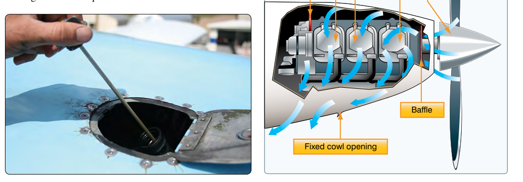
Every piston aircraft engine produces enormous amounts of heat as a byproduct of combustion. In fact, of all the energy released by burning fuel, roughly one-third goes to useful power, one-third exits through the exhaust, and one-third must be carried away by the cooling system. On air-cooled engines — the type found on the vast majority of general aviation piston aircraft — the cowling is the primary structure that makes this heat removal possible. Far from being a simple aerodynamic fairing, the cowling is a precision-engineered duct that captures, directs, and expels cooling air in a carefully controlled manner. Understanding cowling design is therefore central to understanding why engines survive the thermal stress of flight, and it is a recurring topic in FAA Powerplant knowledge testing.
This article covers how cowlings work, why their geometry and baffling matter, the role of cowl flaps, and what can go wrong when cowling components are damaged, improperly installed, or ignored during preflight and maintenance.
How Cowling Design Controls Cooling Airflow
The fundamental job of the cowling is to create a pressure differential between the air entering the front of the engine compartment and the air leaving the rear. Incoming ram air — air forced into the cowl opening by the aircraft's forward motion and the propeller slipstream — creates a high-pressure plenum above the cylinders. The lower rear of the cowling, where air exits around the firewall and through cowl flap openings, is a low-pressure zone. This pressure difference drives air down and around the cooling fins on each cylinder, carrying away heat by convection.
The cowling opening at the front must be sized correctly. Too large, and excess drag is created without a proportional cooling benefit. Too small, and insufficient air volume enters the plenum. Most modern cowling designs follow the NACA cowling concept — a smooth, close-fitting structure that wraps tightly around the engine, pioneered in the late 1920s and refined continuously since. Early NACA cowling testing demonstrated substantial drag reduction compared to earlier exposed-cylinder designs, commonly cited as enabling notably higher airspeeds without additional power, a landmark achievement in aviation engineering that the FAA Airframe and Powerplant handbooks recognize as foundational.
Baffles: The Hidden Key to Uniform Cooling
Cooling air entering the plenum will always take the path of least resistance. Without guidance, it would flow around the outside of the cylinders rather than through the fins where it is needed most. Engine baffles — sheet metal or composite deflectors attached to the cylinders, crankcase, and cowling interior — solve this problem by sealing off pathways that would allow air to bypass the fins. They force all incoming high-pressure air to pass directly through the cylinder fin arrays before reaching the low-pressure exhaust side.
Baffles include inter-cylinder baffles, which separate cylinders from one another to ensure each receives its share of cooling airflow, and baffle seals (sometimes called blast tubes or ramp seals), which are rubberized or fabric strips that close the gap between rigid sheet-metal baffles and the cowling interior surface. These seals are critical: even a small gap allows high-pressure air to escape around the baffles rather than through the fins, significantly reducing cooling effectiveness. The FAA Aviation Maintenance Technician Powerplant Handbook (FAA-H-8083-32) specifically notes that deteriorated or missing baffle seals are a leading cause of excessive cylinder head temperatures (CHT).
During maintenance inspections, technicians must examine every baffle seal for cracking, hardening, tears, or compression set. Seals that no longer make firm contact with the cowling should be replaced immediately. Rigid baffles should be checked for cracks, corrosion, and proper security — a crack that progressively widens in flight creates an increasingly large bypass path for cooling air.
Cowl Flaps: Managing Cooling on Demand
At cruise altitudes with high airspeed, ram air pressure and the large differential across the engine can provide more cooling than is needed, and the added drag of a fully open exit is undesirable. During takeoff and climb, however, the engine is at high power output and the airspeed is relatively low, meaning ram pressure is reduced and the engine produces maximum heat. Cowl flaps address this variable demand by giving the pilot (or the aircraft's design) the ability to change the size of the cooling air exit area.
Opening the cowl flaps enlarges the exit area, increasing the pressure differential and pulling more air through the fins — essential for high-power, low-speed operations. Closing the cowl flaps reduces exit area, conserving heat during cold-weather operations and reducing drag in cruise. Standard procedure taught in the Airplane Flying Handbook (FAA-H-8083-3) is to open cowl flaps before takeoff and during climb, then gradually close them as airspeed increases in cruise once CHT has stabilized within normal range. After landing, cowl flaps are generally left open during the taxi and run-up phases to avoid heat soak.
Some aircraft use fixed cowl openings without adjustable flaps, relying entirely on cowling geometry to provide adequate cooling across all flight regimes. These designs must be carefully validated during certification to ensure they cool adequately during the most demanding conditions (typically a full-power climb on a hot day) without overcooling during high-speed cruise descents.
Why Cowling Design Matters: Safety and Engine Longevity
Cylinder head temperature is the single most important indicator of whether the cooling system is working. Maximum CHT limits vary by engine manufacturer and are specified in the engine type certificate data sheet and the Aircraft Flight Manual/POH, with redline limits commonly cited around 460°F for many Lycoming and Continental engines. Above the applicable limit, metal fatigue, detonation risk, and oil breakdown accelerate rapidly. Sustained high CHT causes warped cylinder heads, cracked cylinders, stuck valves, and accelerated wear of piston rings and valve guides. These are not abstract concerns — they shorten engine TBO significantly and create acute safety hazards.
Conversely, shock cooling — a rapid decrease in CHT caused by sudden power reduction combined with high airspeed, such as in an abrupt descent — is generally described as a source of thermal stress from uneven contraction of cylinder components. While the FAA and engine manufacturers advise managing power reductions gradually as a precaution, the actual magnitude of mechanical damage risk from shock cooling remains debated and is not firmly quantified in FAA guidance, so it should be treated as a recommended precaution rather than a rigorously established hazard mechanism.
Cowling damage from bird strikes, ramp incidents, or improper panel fastening can alter airflow paths in unpredictable ways. A bent cowling panel that creates a gap may dump high-pressure air overboard before it passes through the fins, leading to localized hot spots on certain cylinders even while others remain cool. This kind of asymmetric cooling is difficult to detect without monitoring individual cylinder CHT, which is why multi-probe CHT/EGT monitoring systems are standard on modern aircraft and recommended for all piston operations.
Key Numbers and Rules
- Typical maximum CHT limits: commonly cited around 460°F for many Lycoming/Continental engines, but always consult the specific engine manufacturer's data, Type Certificate Data Sheet, and the Aircraft Flight Manual for the applicable limit.
- Cowl flap operation: Open before takeoff, maintain open during climb; close progressively during cruise after CHTs stabilize.
- Baffle seal gap: Any visible gap between baffle seal and cowling interior reduces cooling; seals should make full contact around the entire perimeter.
- Pressure differential: Effective cooling requires high pressure above the cylinders and low pressure below/aft — cowling geometry and baffles create and maintain this differential.
- CHT monitoring: FAA-H-8083-32 emphasizes using CHT as the primary indicator of cooling system health; EGT is primarily used to monitor fuel mixture.
- Annual inspection: 14 CFR Part 43, Appendix D requires inspection of the engine section and cowling, including baffles, for cracks, damage, and loose or missing fasteners.
Common Test Traps
- Confusing CHT and EGT roles: CHT monitors cooling system effectiveness; EGT primarily indicates mixture setting. A test question may ask which instrument shows cooling efficiency — the answer is CHT, not EGT.
- Assuming cowl flaps are only for hot weather: Cowl flaps should be open during any high-power, low-airspeed operation regardless of ambient temperature, because power output — not just outside air temperature — drives cylinder heat load.
- Overlooking baffle seals during inspection: Test questions often focus on what causes elevated CHT. A missing or damaged baffle seal is a classic correct answer because it allows cooling air to bypass the fins.
- Confusing inlet and exit sizing: Students sometimes assume a larger cowling inlet always means more cooling. In fact, the pressure differential across the engine matters most — both the inlet and exit must be properly sized and the baffles must be intact for the system to work.
- Forgetting cowl flap position after landing: Leaving cowl flaps closed after landing during engine run-up or extended taxi can allow heat soak to raise CHT significantly. The correct procedure is to open cowl flaps before or during taxi after landing.
Cowling design is one of those topics that connects directly to real-world engine health. Whether you are performing an annual inspection, troubleshooting elevated CHTs, or advising a pilot on climb procedure, understanding the pressure-differential model — high-pressure plenum above, low pressure below, baffles forcing air through the fins — gives you a complete mental picture of why each component exists and what failure looks like. Master this concept and both the FAA test and the ramp become clearer.